¶ Charge Space — Operational Guide
The Charge Space is a self-contained, road-towable mobile device charging station designed for construction sites, events, and remote locations. It provides 48 individually lockable charging compartments, each fitted with a 230V socket, powered entirely by solar energy, lithium-ion batteries, and a backup generator. No mains connection is required for normal operation.
The unit has full VCA type approval for road towing and deploys in under one minute using an integrated hydraulic ram system (see Fig. 21).
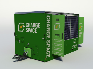
Fig. 1 — Charge Space in deployed configuration.
¶ Contents
- Technical Specifications
- Unit Layout — External
- Unit Layout — Internal
- Daily Checks
- Transporting the Unit
- Deploying on Site
- Power System
- Controls and Key Components
- Charging Compartments
- Fire Suppression System
- Electrical System — Wiring Reference
- Software and Control Architecture
- Diagnostics
- Maintenance
- Warranties
- Legal and Safety
¶ Technical Specifications
| Parameter | Value |
|---|---|
| Charging outputs | 48 × single-phase 230V 50Hz 3-pin sockets |
| Compartments | 48 lockable, 4-digit combination lock (KitLock); numbered 1–48 in Banks 1–4 |
| Solar array | 3,150W — 10 × 315W panels (4 roof-mounted, 6 wall-mounted) |
| Battery capacity | 2 × 5.12 kWh lithium-ion = 10.24 kWh total |
| Inverter/charger | Victron Quattro 48/8000 |
| Solar charge controllers | 2 × Victron SmartSolar MPPT 150/70 |
| Generator | REDBOX 6 kVA Stage V (Infinity engine) |
| Generator fuel | HVO biofuel, diesel, or blend (no biodiesel) |
| Generator service interval | 2,000 operating hours |
| External AC input | 230V single-phase 16A (optional) |
| Lighting | 24V LED, PIR-activated (internal and external) |
| Power management | Victron Cerbo GX + Node-RED automation |
| Tyre pressure (12/16ft) | 70 psi — 215/75 R16, load rating 113, rim 5.5J×16 |
| Wheel nut torque | 160 Nm |
| Maximum tow speed | 50 mph (80 km/h) |
| Unit dimensions (body) | 3,650 × 2,300 × 2,630 mm (L × W × H) |
| Towing length / height | 4,775 mm / 2,900 mm |
| Net weight | 2,211 kg |
| Fuel tank capacity | 50 litres |
| Axle rating | Single axle, 2,500 kg |
| Starting battery | 12V AGM leisure battery (generator start circuit only) |
¶ Unit Layout — External
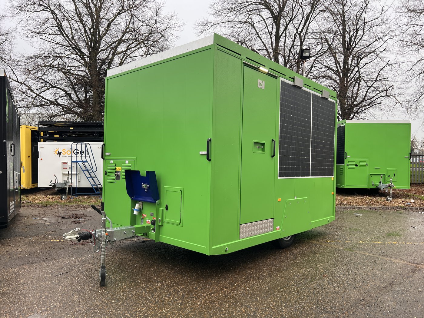
Fig. 2 — Front left, unit on road wheels ready for towing.
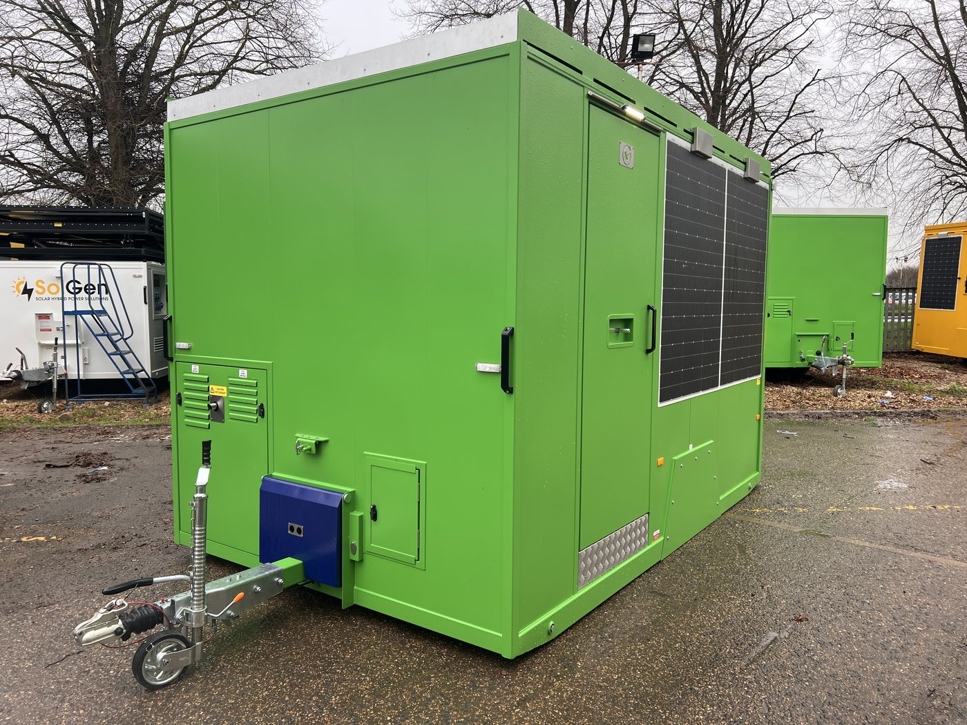
Fig. 3 — Front left, unit deployed on site with anti-vandal cover in lowered position.
The rear face of the unit carries the main solar array — six 315W wall-mounted panels arranged in a 3×2 configuration, plus four further panels on the roof (see Figs. 4 and 5). Positioning the unit with the tow hitch pointing south maximises exposure of the rear wall panels, which are the primary generation surface, particularly in winter months.
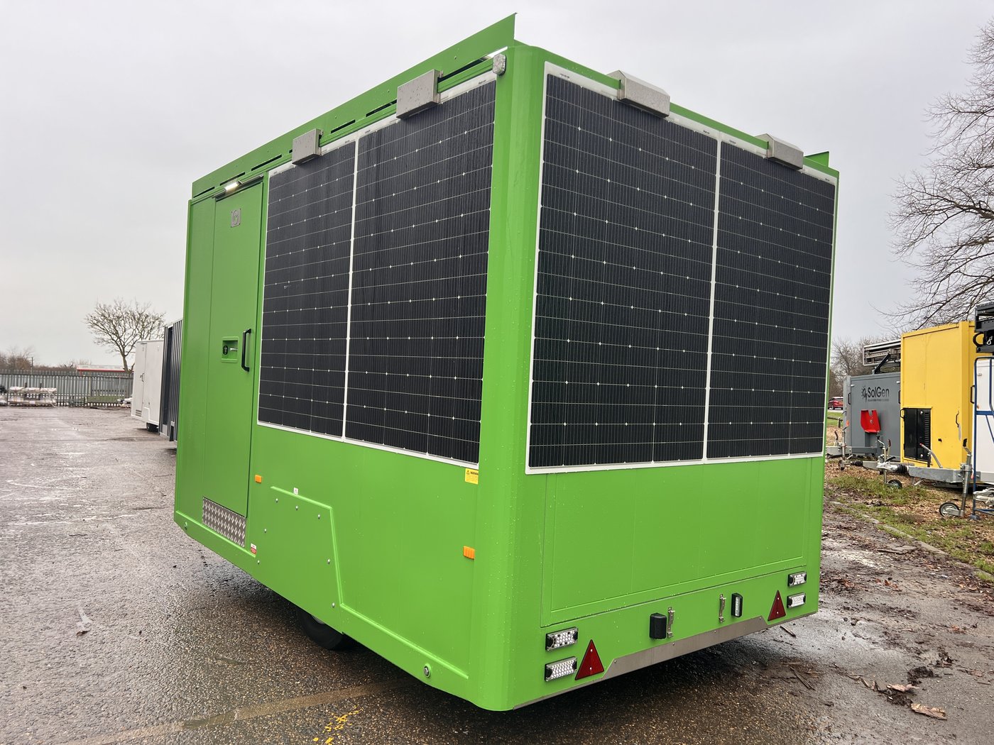
Fig. 4 — Rear left, on road wheels. The six wall-mounted solar panels dominate the rear face.
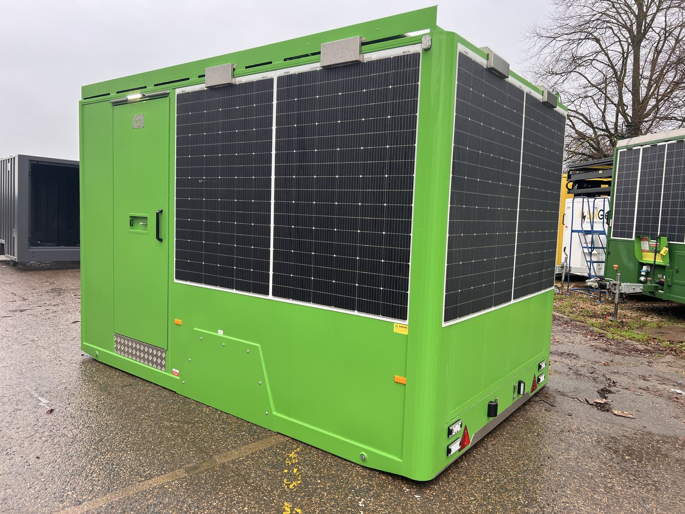
Fig. 5 — Rear left, deployed on hydraulic rams. Ram cylinders are visible beneath the chassis.
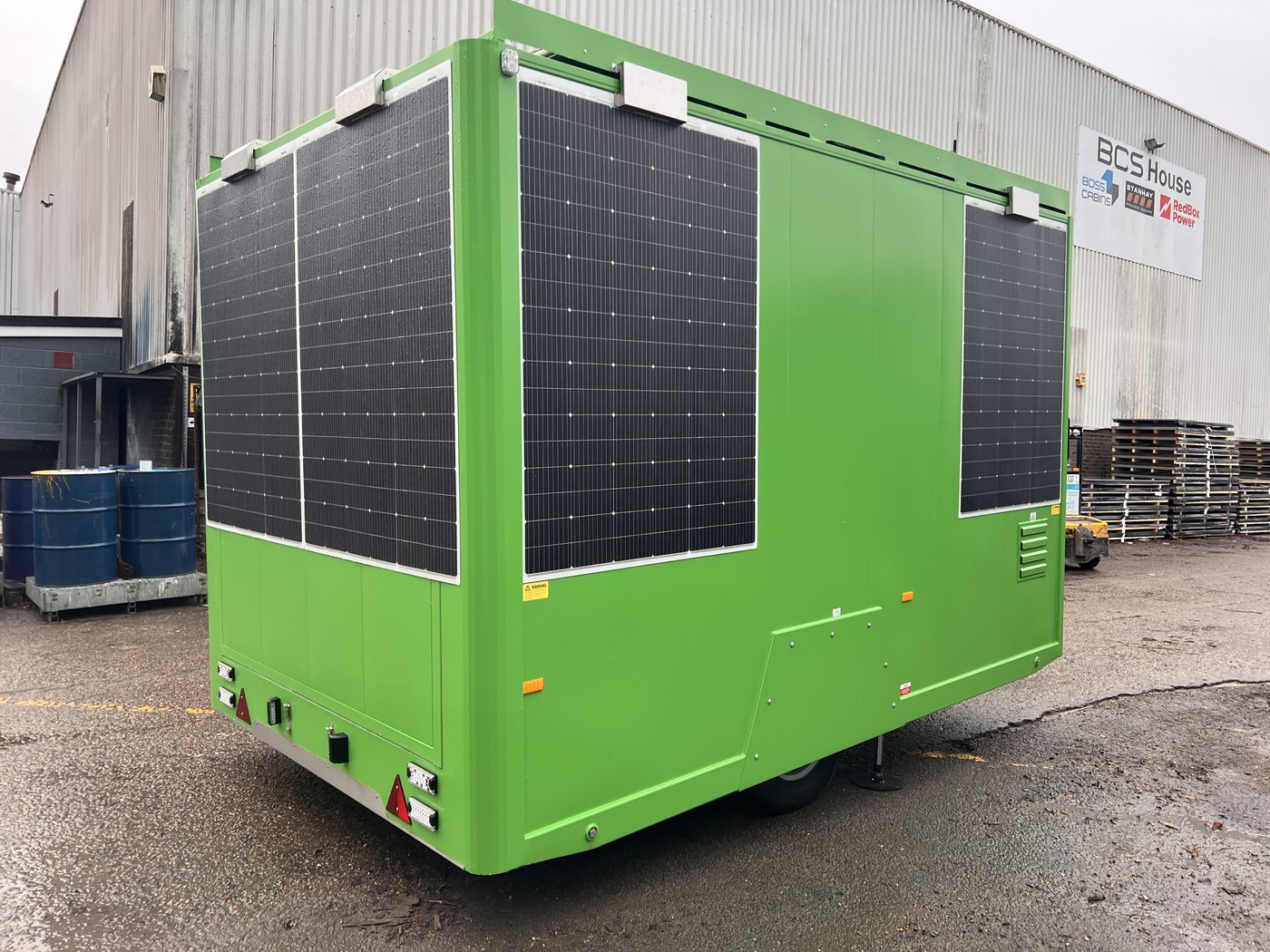
Fig. 6 — Rear right, on road wheels.
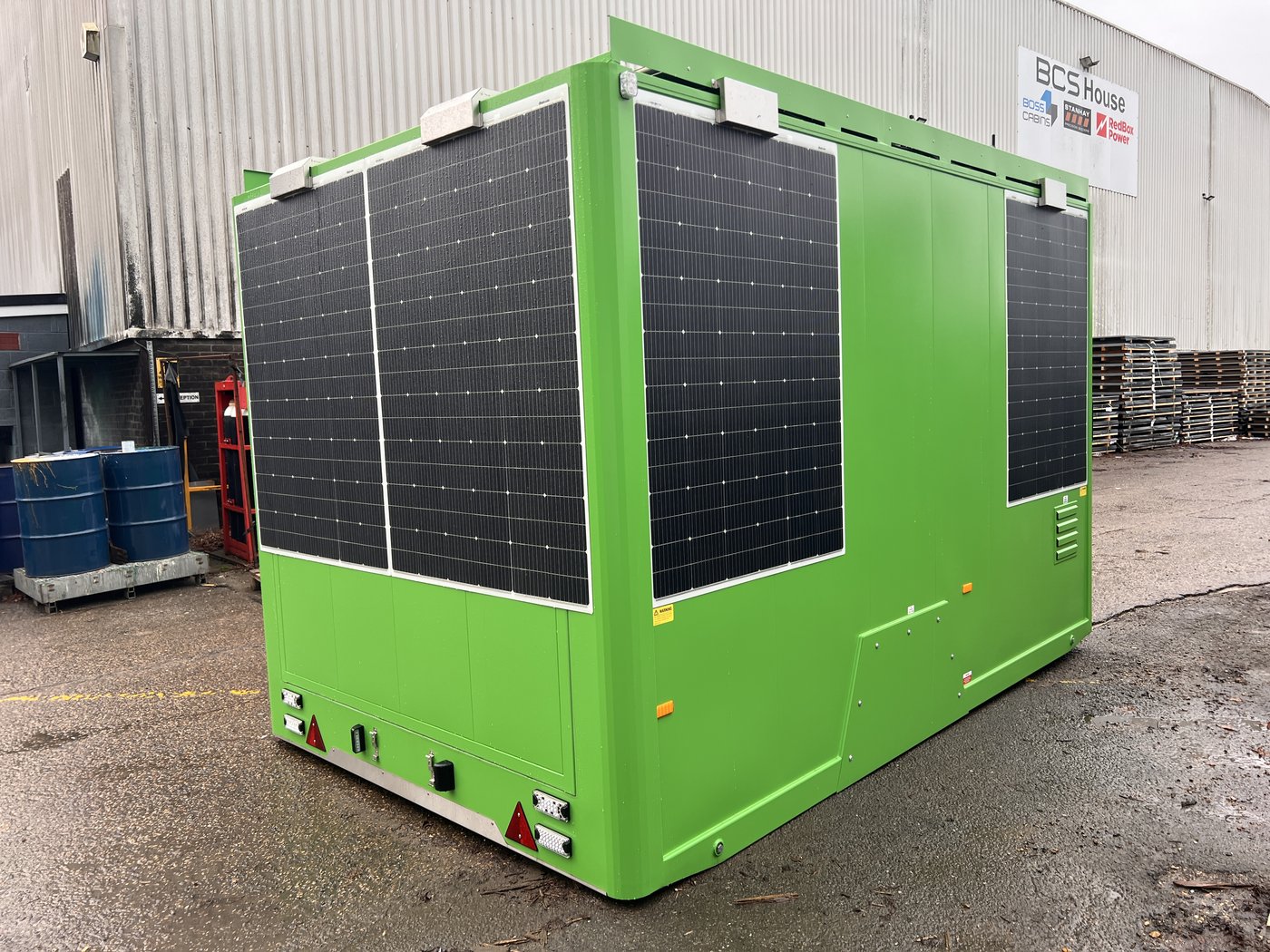
Fig. 7 — Rear right, deployed.

Fig. 43 — Rear left, factory/yard. Unit deployed on hydraulic rams; all six rear wall-mounted solar panels visible.

Fig. 44 — Rear right, factory/yard. Access door closed; road lighting cluster and panel detail visible.
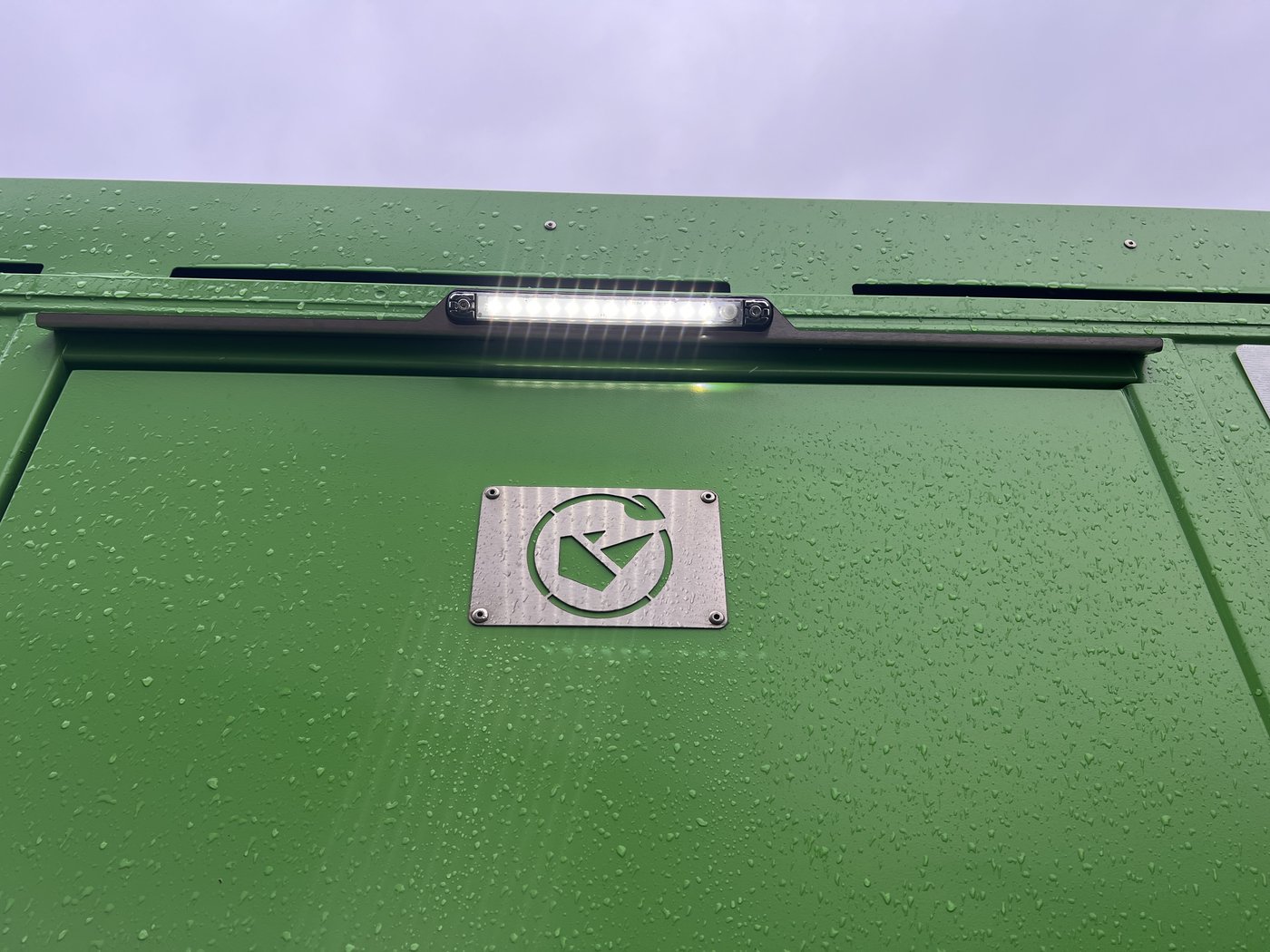
Fig. 8 — Exterior PIR-activated LED light and Boss Cabins badge above the access door.
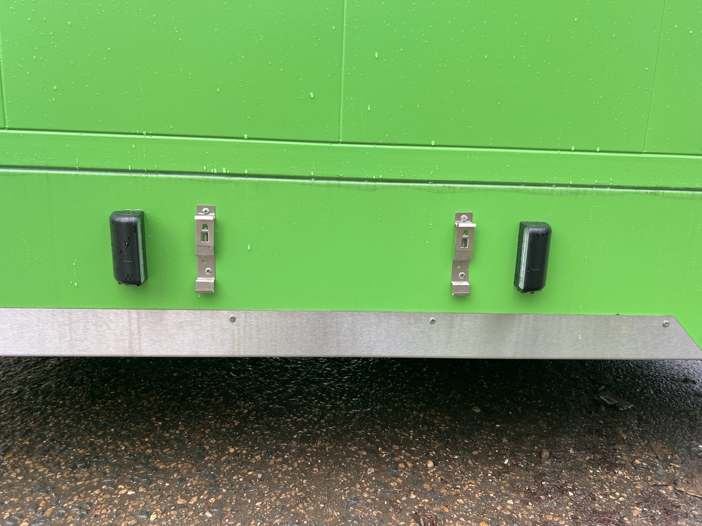
Fig. 9 — Lower side panel catches securing the removable access panels. Stainless steel anti-wear sill at base.
¶ External Component Reference
| Ref | Item |
|---|---|
| 1 | Roof-mounted solar panels (4 × 315W) |
| 2 | Wall-mounted solar panels (6 × 315W) |
| 3 | Extendable solar panel roof tray |
| 5 | Parking brake |
| 6 | 50mm ball coupler with inertia overrun brake / pin and eye coupler |
| 7 | Breakaway activation cable |
| 8 | Jockey wheel |
| 9 | Road lighting connection socket |
| 10 | Anti-vandal cover |
| 12 | SOLARTrack™ telemetry antenna |
| 15 | Fuel compartment (fuel gauge and filler) |
| 17 | Side marker reflectors/lights* |
| 18 | End outline marker lamps* |
| 19 | Hydraulic lift cylinders (rams) |
| 20 | Stop/tail/direction indicator lamps* |
| 21 | Number plate holder |
| 23 | Stainless steel anti-wear corner protection |
| 25 | Axle release bolts |
| 26 | Detachable wheel arch |
| 27 | Low-level lifting points |
* Road-legal items — it is an offence to tow without these fitted and functioning correctly.
¶ Unit Layout — Internal

Fig. 10 — Interior from front right. Charging compartments occupy both side walls and the rear.
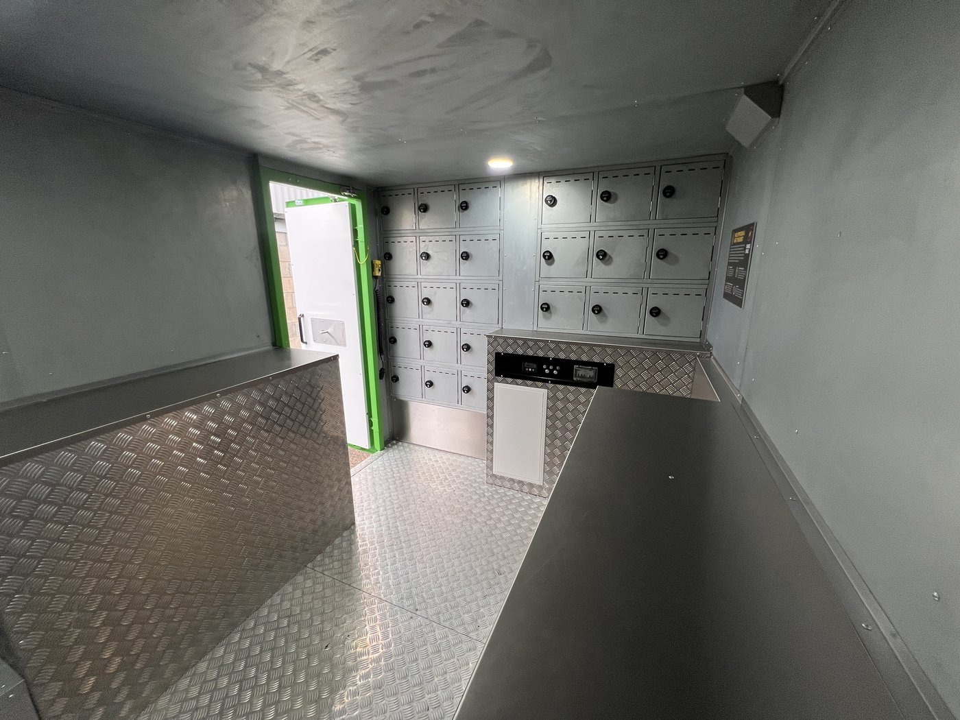
Fig. 11 — Interior from rear right. Central counter unit and display screen visible.
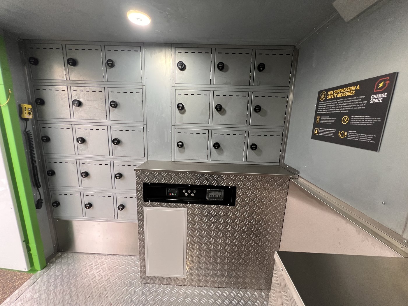
Fig. 12 — Rear wall showing compartments, display screen, and fire safety information panel.
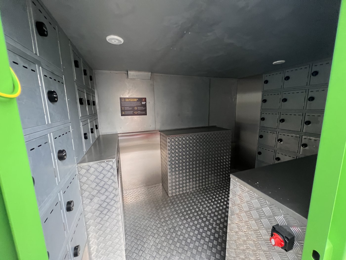
Fig. 13 — View from doorway. Red E-stop button visible lower right; fire safety information panel on far wall.
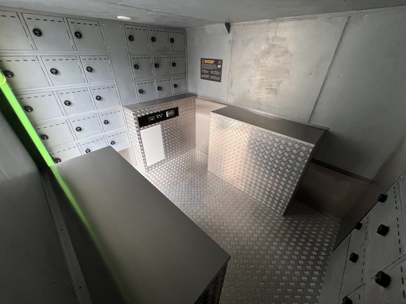
Fig. 14 — Interior overhead view, all compartment doors closed.
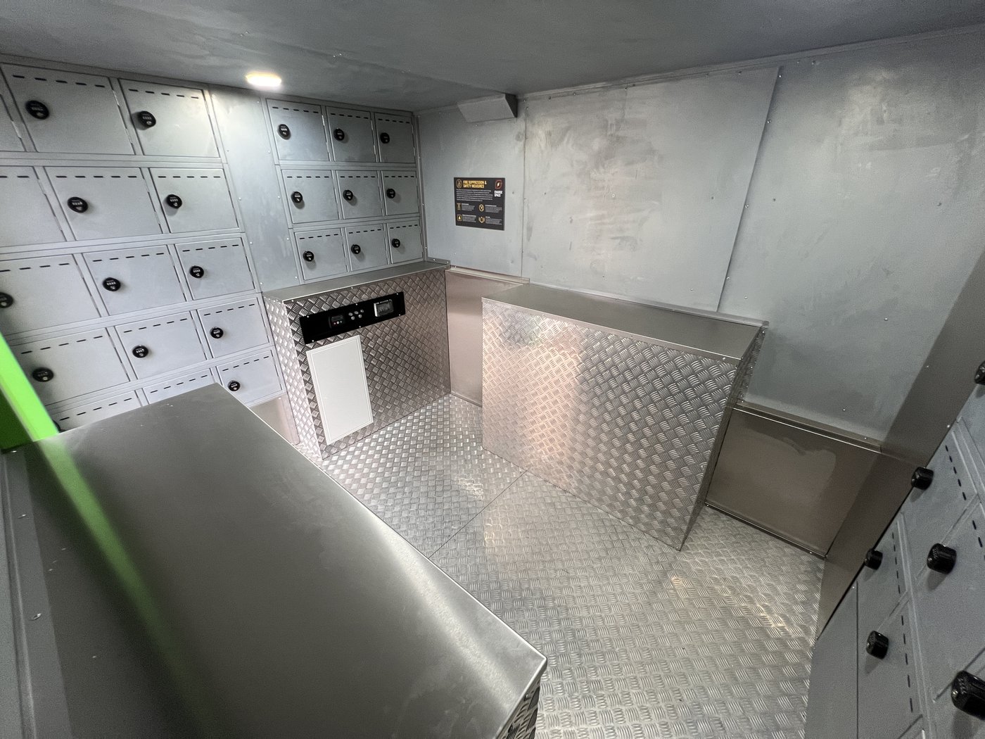
Fig. 15 — Interior at counter level, showing the full right-hand compartment bank.
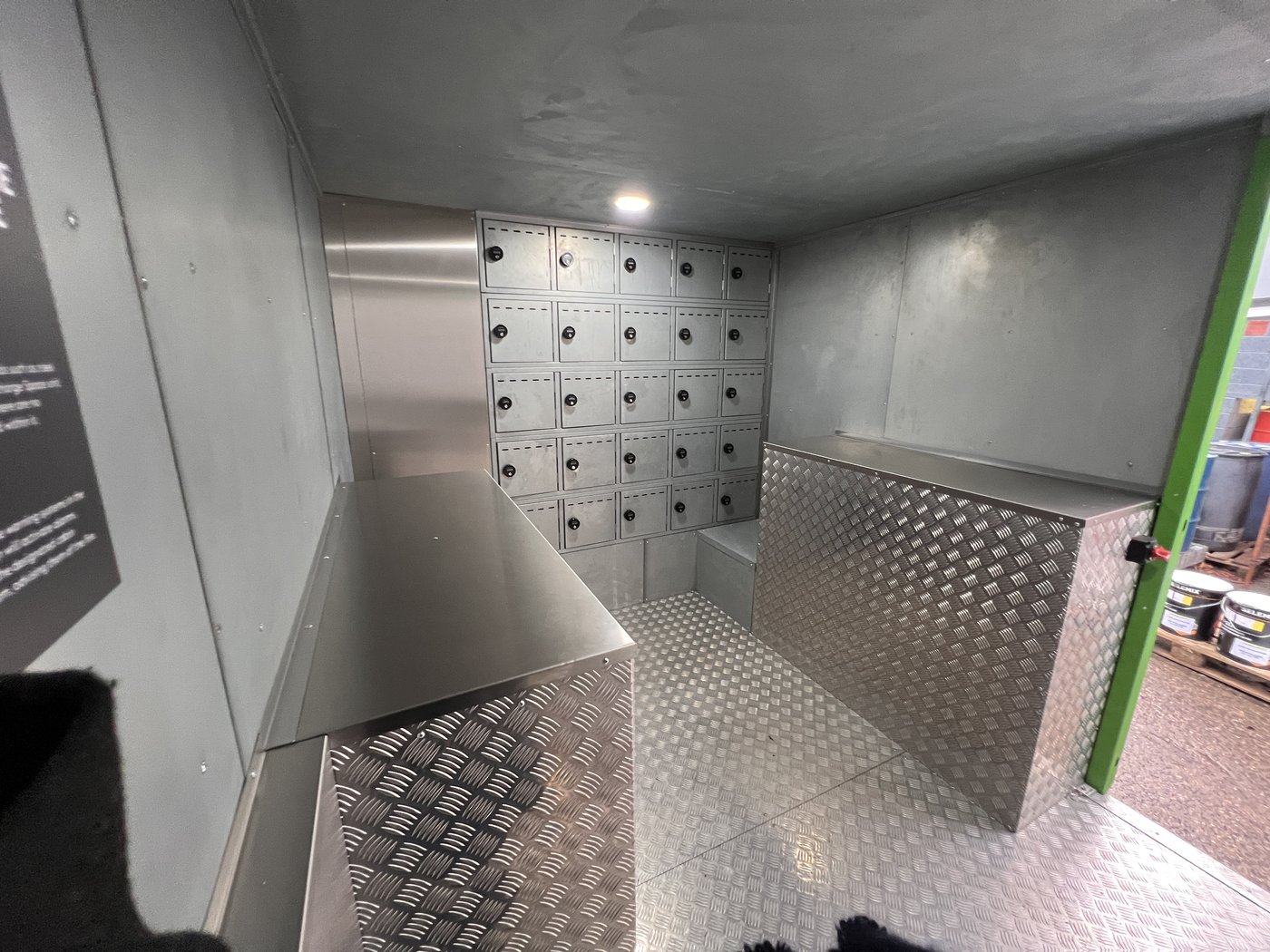
Fig. 49 — Interior from door (clean/new unit). Compartments on right-hand and rear walls; chequerplate counter and floor.
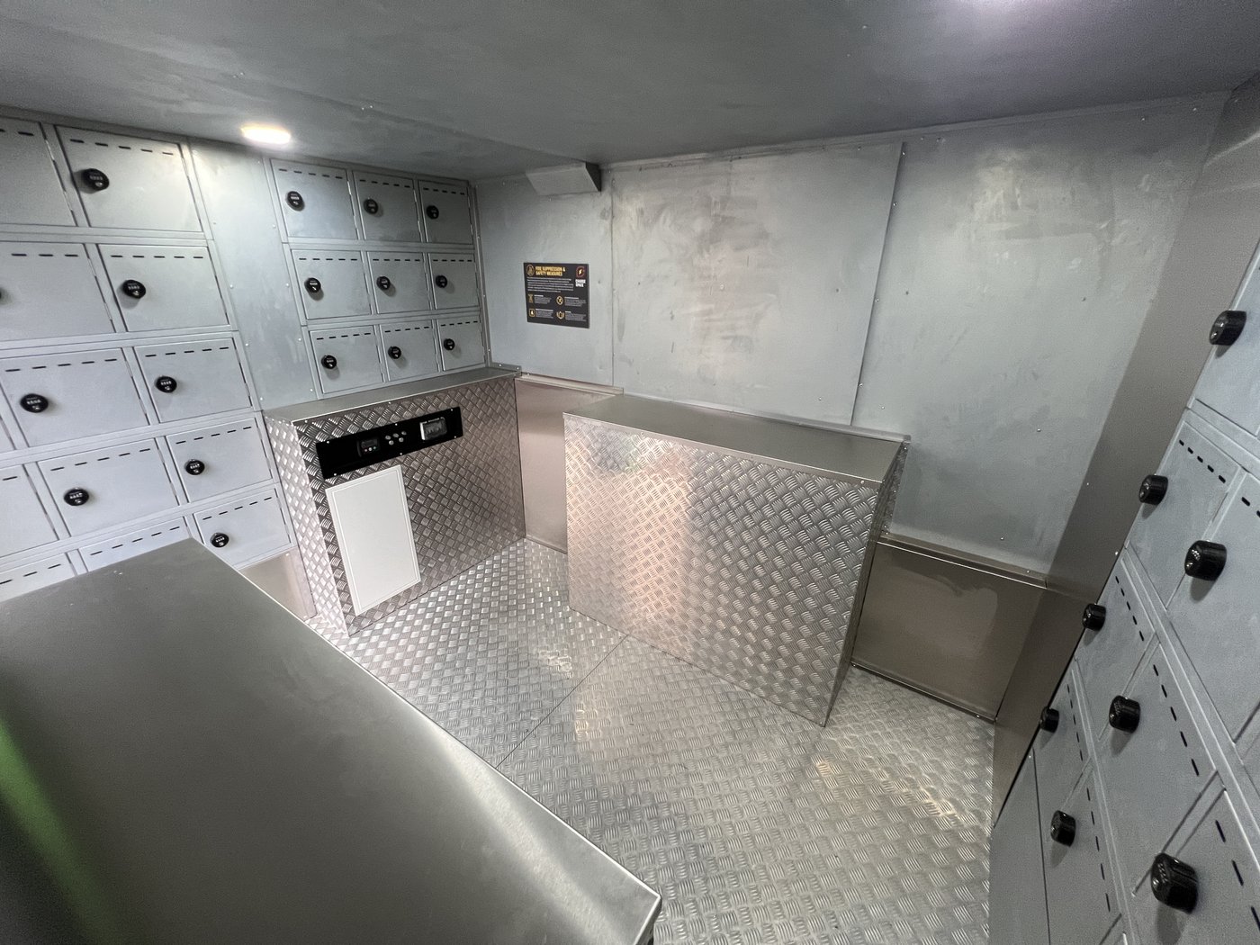
Fig. 50 — Interior overview from rear. Display screen centre; compartments on all walls; PIR ceiling light above.
¶ Daily Checks
Before and during operation, check the following each day:
- Fuel level — check the display screen or the fuel gauge in the front locker (Fig. 22)
- Generator oil — check using the orange dipstick; top up via the same filler cap using SAE 15W-40. Do not exceed the MAX mark
- E-Stop — must be released (twisted clockwise to the OUT position) for electrics to operate
- Display screen — check for any warnings or alerts (Fig. 12)
- Solar panels — visually check that panels are clear of debris and not shaded
Generator oil specification: SAE 15W-40
¶ Transporting the Unit
¶ Pre-Towing Checklist
Before every move:
- Press the E-Stop IN to isolate electrics and prevent the exterior PIR lights activating on the road
- Ensure all loose items are stowed — do not use the unit as a payload trailer (overweight risk)
- Lock all doors, windows, and shutters
- Disconnect all umbilical connections
- Maximum towing vehicle GVW: 18,000 kg
¶ Preparing for Towing (12ft/16ft Units)
- Unlock the anti-vandal cover with the key; raise it to the towing position; engage the anti-loose fastener and safety pin
- Raise the parking brake lever
- Release the E-Stop (twist clockwise) so that cabin electrics are active
- Press and hold the silver button for 3 seconds to activate the hydraulic ram system (see Fig. 17). The system remains active for 5 minutes — all other electrics are off during ram activation
- Connect the remote control 7-pin plug to the front socket
- Press the button furthest from the wire to lower the rams and raise the cabin until the wheels clear the ground
- Lift the spring bolt, push in the handle to engage the axle locking mechanism, then release the spring bolt over the washer
- Press the button closest to the wire to retract the rams and lower the unit onto its road wheels and jockey wheel
- Unplug the remote control and stow it inside the cabin
- Press the E-Stop IN before towing
- Insert the towing vehicle's number plate into the holder clip
¶ Attaching to the Towing Vehicle — Ball Hitch
- Cabin raised, wheels on floor, rams retracted; apply the parking brake
- Turn the jockey wheel anti-clockwise to raise the coupling head above the tow ball; manoeuvre the vehicle under the coupler
- Raise and hold the coupling head handle; turn the jockey wheel clockwise to lower the coupling onto the ball
- Release the handle — allow it to snap closed; verify that it is fully engaged
- Attach the breakaway cable to the tow hitch; ensure it is secure
- Connect the lighting cable; check that all road lights are functioning
- Raise the jockey wheel clear of the ground; rotate the assembly 90° to lie parallel with the tow bar
- Release the parking brake
¶ Attaching to the Towing Vehicle — Pin and Eye
- Cabin raised, wheels on floor; apply the parking brake
- Adjust the eye height using the jockey wheel; align with the pin holes on the tow bar
- Insert the coupling pin; secure with the safety clip
- Attach the breakaway cable; connect the lighting cable
- Raise and stow the jockey wheel; release the parking brake
¶ Uncoupling — Ball Hitch
- Level ground; inspect the underside for obstacles; apply the parking brake
- Drop the jockey wheel to the ground; tighten the retainer
- Disconnect the lighting cable
- Detach the breakaway cable
- Lift the handle behind the tow hitch; turn the jockey wheel anti-clockwise to raise the tow bar above the ball
- Remove the vehicle
- Raise and stow the jockey wheel
¶ Uncoupling — Pin and Eye
- Level ground; apply the parking brake; drop the jockey wheel
- Disconnect the lighting cable; detach the breakaway cable
- Remove the safety clip; withdraw the coupling pin
- Raise and stow the jockey wheel
¶ Deploying on Site
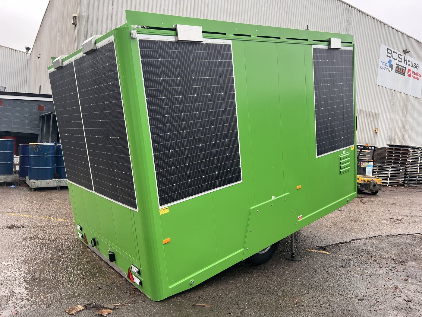
Fig. 21 — Unit raised on hydraulic rams. Wheels are clear of the ground at this stage.
- On level ground, uncouple from the towing vehicle with the parking brake applied; move the vehicle clear
- Release the E-Stop (twist clockwise)
- Press and hold the silver button for 3 seconds to activate the ram system (Fig. 17)
- Connect the remote control; press the button furthest from the wire to raise the cabin
- Raise until the wheels are clear of the ground (Fig. 21)
- Disengage the axle locking mechanism: open the spring bolt, pull the handle out, then release the spring bolt
- Press the button closest to the wire to retract the rams — the unit lowers to the ground
- Release the parking brake; unplug and stow the remote control
During deployment, the unit must be uncoupled from the towing vehicle. The remote control must be unplugged whenever raising or lowering is not in progress.
¶ Anti-Vandal Cover
To lower into the deployed position:
- Release the anti-loose fastener and safety pin
- Lower the cover over the electrics area
- Lock with the key; remove the key; close the lock seal
To raise for towing, reverse the procedure.
¶ Lifting by Crane
The unit has low-level lifting eyes (removable; stored inside the unit when not in use).
- Remove the plugging bolt from each eye hole
- Screw in a lifting eye until it makes face-to-face contact with the cabin side
- Repeat for all four corners
- Always use spreader bars with straps or chains — required to protect the solar panel skirts
- Never lash over the top of the cabin — this will damage the solar panels and skirt
Use only Boss Cabins proprietary lifting eyes. One per corner.
¶ Power System
¶ Overview
The SOLARFlow™ system manages three power sources automatically:
- Solar — primary source; charges the batteries during daylight hours
- Battery — supplies all loads from stored energy
- Generator — starts automatically when the battery is low; no manual intervention required
External AC input is an optional override for shore power or mains charging. It requires a manual switching procedure (see below).
The Victron Quattro 48/8000 inverter/charger handles seamless source switching. Remote telemetry via SOLARTrack™ displays battery state of charge (SOC), solar yield, generator runtime, and consumption.
¶ Site Positioning for Maximum Solar Generation
Park the unit with the tow hitch pointing south in an open, unobstructed position. Avoid shade from trees, buildings, bridges, or other structures. In winter months, the side wall panels produce the majority of the electricity.
Do not park in shade or under cover.
¶ Using External AC Power
Use a 32A 230V 50Hz supply only. Do not connect to a PME (Protective Multiple Earth) supply. Minimum cable: 2.5mm², H07RN-F type. Fully uncoil the cable before use to prevent overheating.
The external AC inlet socket is located beneath the anti-vandal cover (Fig. 22). The inlet is a 16A IP67 CEE type socket with a sealing blue cap (Fig. 45). The external RCBO is housed in an IP67-rated weatherproof enclosure recessed into the front panel (Fig. 46).

Fig. 45 — Front underflap: external AC inlet socket (white, 16A IP67), E-stop and control push-buttons, and earth point.
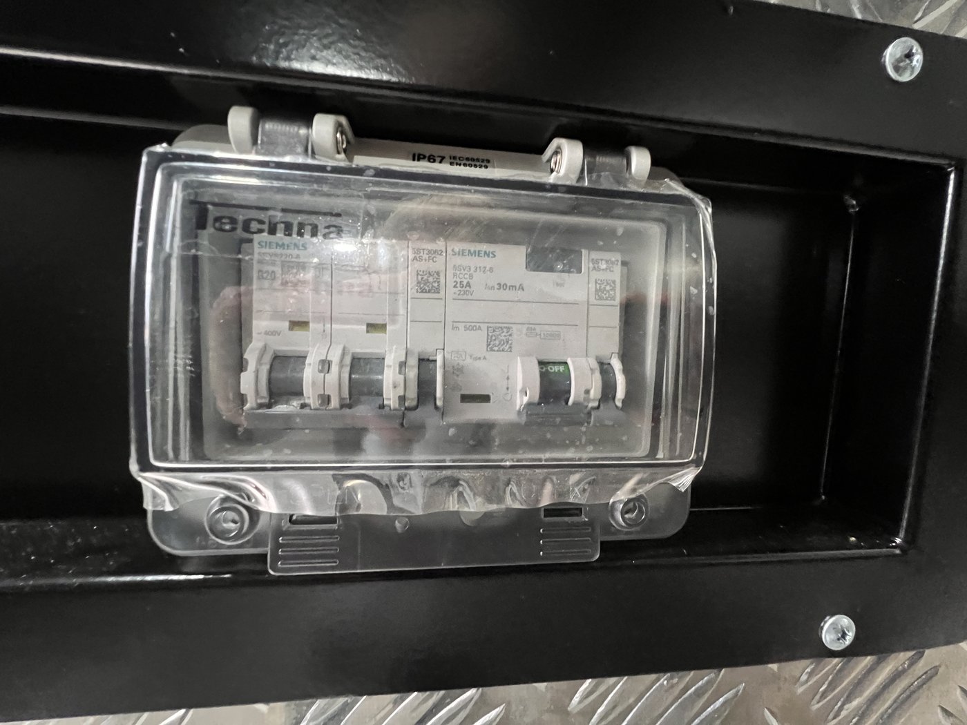
Fig. 46 — External RCBO enclosure. Must be set ON to enable external AC charging; OFF when not in use.
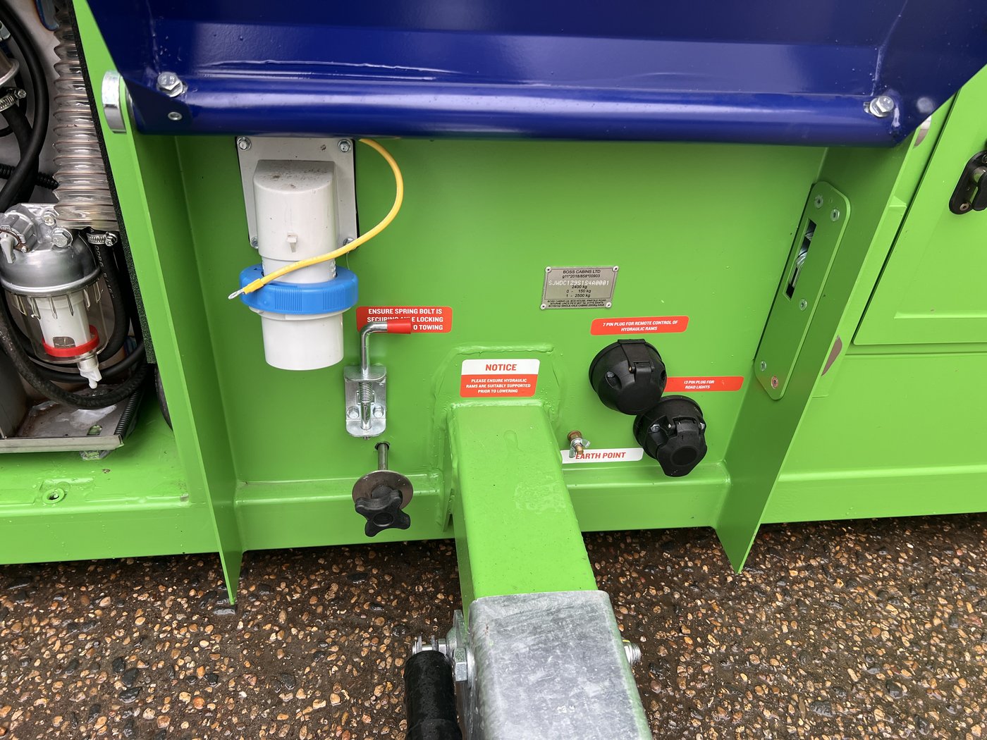
Fig. 22 — Under the anti-vandal cover, showing the external AC inlet socket, fuel filter, and E-stop.
To connect external AC:
- Turn the cabin isolator switch to OFF (Fig. 16)
- Open the inlet socket cover; insert the supply cable connector
- Connect the other end to the site supply outlet
- Set the external socket RCBO to ON
- Turn the cabin isolator switch to ON
To disconnect external AC:
- Set the external socket RCBO to OFF
- Turn the isolator switch to OFF
- Disconnect the cable from both ends
- Turn the isolator switch back to ON to resume normal operation
Caution: If the external RCBO is left in the wrong position when switching back to generator mode, the batteries will drain and the generator will not start.
¶ Battery Protection — Automatic Load Shedding
As the battery SOC drops, loads are shed automatically in the following order:
| Battery SOC | Automatic Action |
|---|---|
| 60% | Power sockets and USB ports turn off |
| 40% | Kettle and microwave turn off |
| 30% | Hot wash/hand dryers turn off; hydraulic rams will not activate |
| 20% | Heater, external LED lights, display screen, and water pumps turn off |
| 15% | Complete isolation — all appliances, lights, and pumps turn off |
¶ Controls and Key Components
¶ E-Stop
The red mushroom-headed E-stop button is located at the lower right of the access door frame (visible in Fig. 13).
- Normal operation: E-Stop must be released (OUT) — twist clockwise to release
- When pressed: isolates all main electrical loads; telemetry, solar chargers, and external chargers remain active
- Before towing: press the E-Stop IN to prevent the exterior PIR lights activating on the road
- For storage: press IN to isolate all electrics
¶ Cabin Isolator Switch
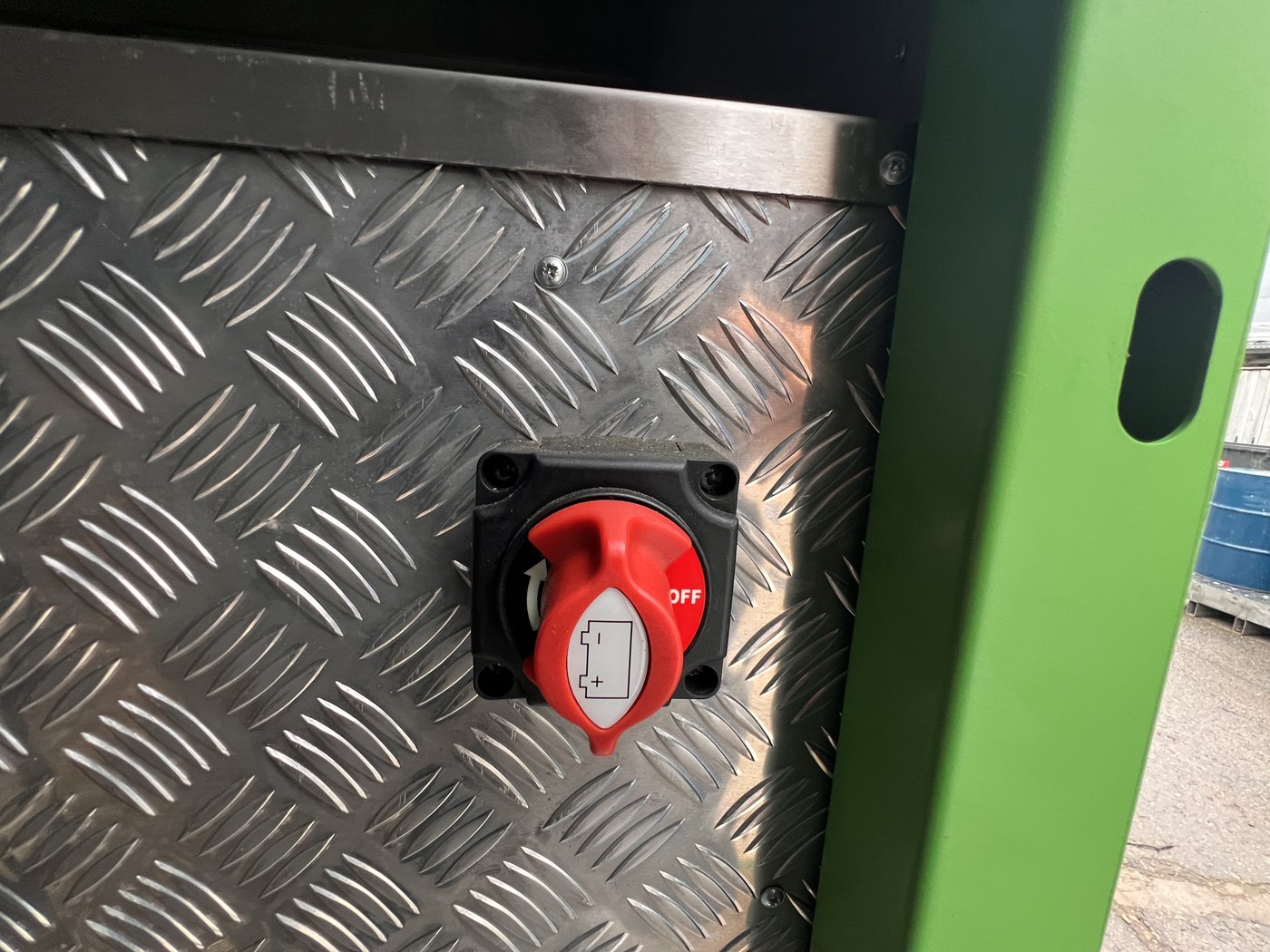
Fig. 16 — Main cabin isolator switch (red rotary disconnect). Shown in the OFF position.

Fig. 51 — Cabin isolator switch, close-up. Rotate to ON for normal operation.
The cabin isolator (Fig. 16) is a hard-wired rotary disconnect that cuts all power, including telemetry. It is used for storage or major maintenance only. When OFF: no lights, no charging, no telemetry.
¶ Control Panel — Circuit Breakers and Hydraulic Buttons
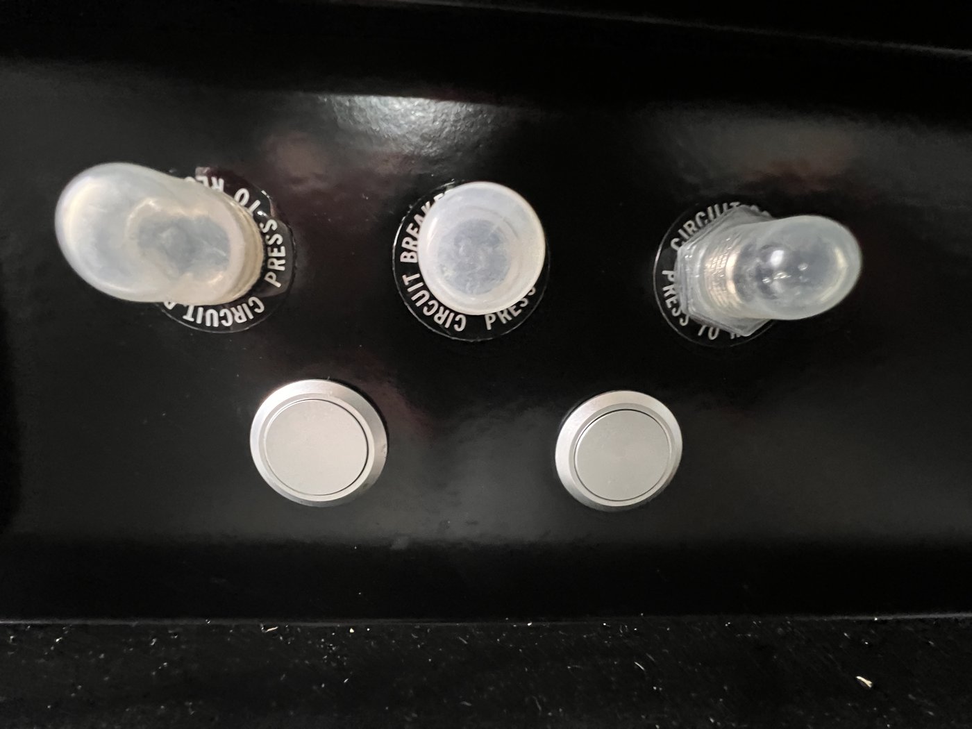
Fig. 17 — Control panel showing three circuit breakers (upper) and two hydraulic pushbuttons (lower).
| Control | Function |
|---|---|
| Three circuit breakers (black, upper row) | Pop-out trip indicators; press to reset |
| Silver button (hold 3 sec) | Activates the hydraulic ram system for 5 minutes |
| Silver button (furthest from wire) on remote | Extends rams — raises cabin |
| Silver button (closest to wire) on remote | Retracts rams — lowers cabin |
¶ PIR Lighting
- Interior: 24V LED circular ceiling light (Fig. 48), auto-on when the unit is occupied; auto-off after 10 minutes of inactivity. If lights switch off while a person is seated, any movement will re-trigger them
- Exterior: 24V LED bar above the door (Fig. 8), controlled by PIR sensor combined with a daylight sensor — activates in low-light conditions only
- Before towing: press the E-Stop IN to disable the exterior PIR light
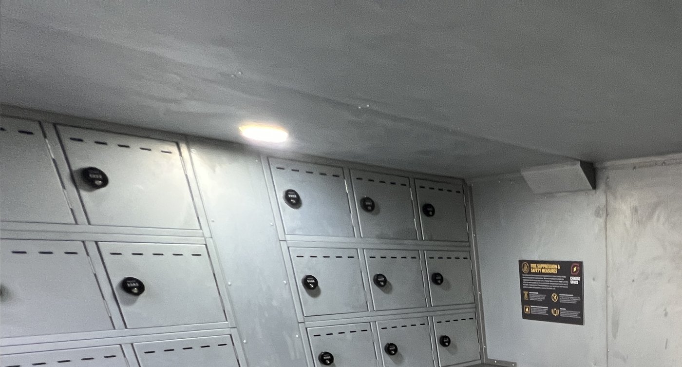
Fig. 48 — Interior PIR-activated LED ceiling light. Auto-on/off; no manual switch required.
¶ Charging Compartments
The unit contains 48 individually lockable charging compartments arranged on both side walls and the rear wall (Figs. 10–15). Compartments are individually numbered 1–48 and organised into four banks (Bank 1 to Bank 4), as labelled on the decals inside the unit. Each compartment is fitted with:
- One 230V 50Hz 3-pin socket (Fig. 19)
- A KitLock 4-digit combination lock with key override (Fig. 18)
- An individual heat and smoke sensor connected to the fire suppression system
- Ventilation slots for airflow
- Thermal isolation from adjacent compartments
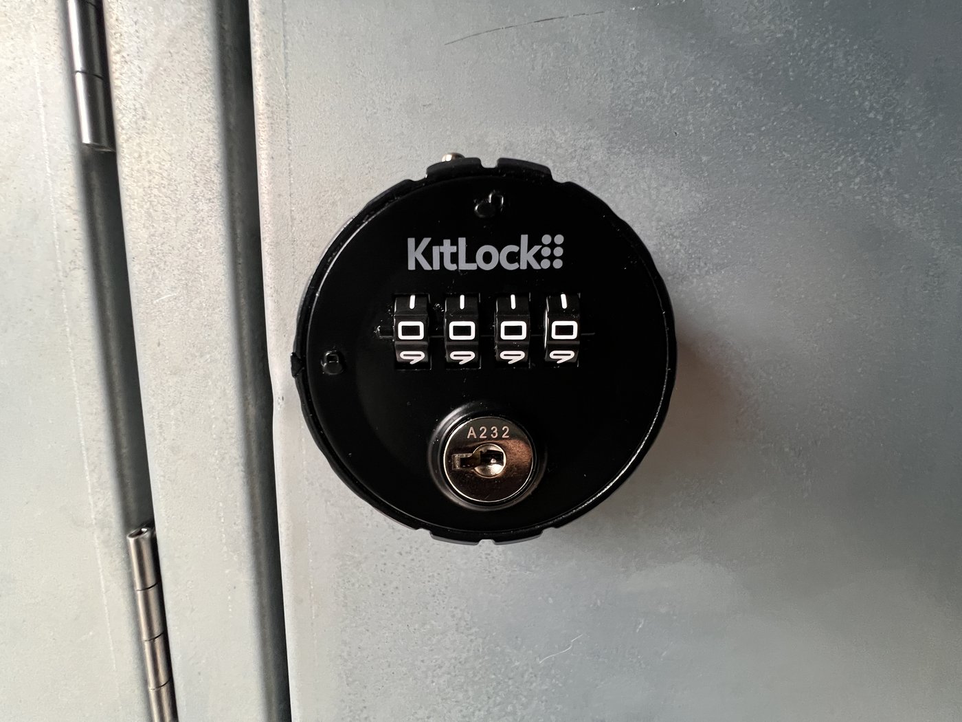
Fig. 18 — KitLock combination lock with key override. Each compartment has an individually settable code.

Fig. 19 — Inside a charging compartment showing the 230V socket and fire suppression module above.
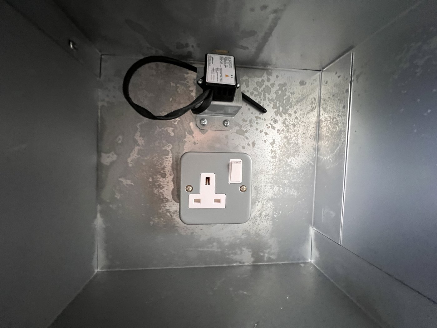
Fig. 47 — Compartment interior: 13A switched socket (bottom) and heat/smoke sensor (top). Galvanised steel walls.
¶ Display Screen / SOLARTrack™
The wall-mounted display screen (visible in Figs. 11–12) shows: battery level, solar generation (W), current consumption (W), fuel level, and any active warnings. Check the display screen first if the unit is not operating correctly. Common warnings:
- E-Stop pressed
- Rams enabled (all other electrics off during ram activation)
- Low fuel
¶ Fire Suppression System
The fire suppression system is designed specifically for the risks associated with charging lithium-ion batteries and personal electronic devices.
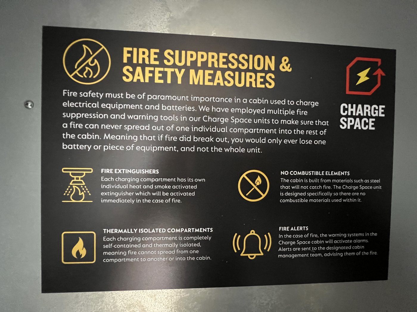
Fig. 20 — Fire suppression and safety measures information label, as fitted inside the unit.
Detection: A combined optical smoke and fixed heat detector (Fig. 35 — wiring diagram 10) is installed inside the unit. Each compartment additionally has its own individual heat and smoke sensor.
Automatic response on smoke or heat detection:
- The Victron Quattro inverter is commanded OFF — all charging sockets lose power immediately
- Generator start is blocked
- A remote fire alert is sent to the cabin management system
Design principles:
- All-metal interior construction — no combustible materials
- Each compartment is thermally isolated — fire cannot spread between compartments
- Individual extinguishing mechanism per compartment, activated automatically on detection
Smoke detection has the highest priority in the control architecture — it overrides all other controls, including generator demand signals.
For wiring details of the smoke/heat detector circuit, see Fig. 35.
¶ Generator
¶ Overview
REDBOX 6 kVA Stage V generator with Infinity engine. Runs on HVO biofuel, diesel, or any blend of the two. HVO reduces greenhouse gas emissions by up to 90% compared with conventional diesel. Do not use biodiesel.
Service interval: 2,000 operating hours.
Starting battery: A separate 12V AGM leisure battery provides the cranking power to start the generator. This battery is charged via the main system and does not supply any other loads. If the generator fails to crank, check the AGM battery voltage and connections.

Fig. 42 — Generator compartment fully open. All pre-start checks (oil, fuel) are carried out at this access point.
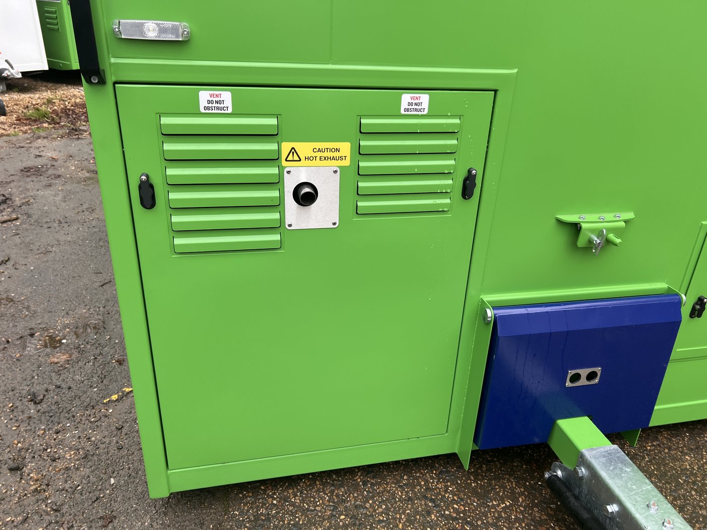
Fig. 23 — Generator compartment with cover fitted. Do not obstruct the ventilation louvres.
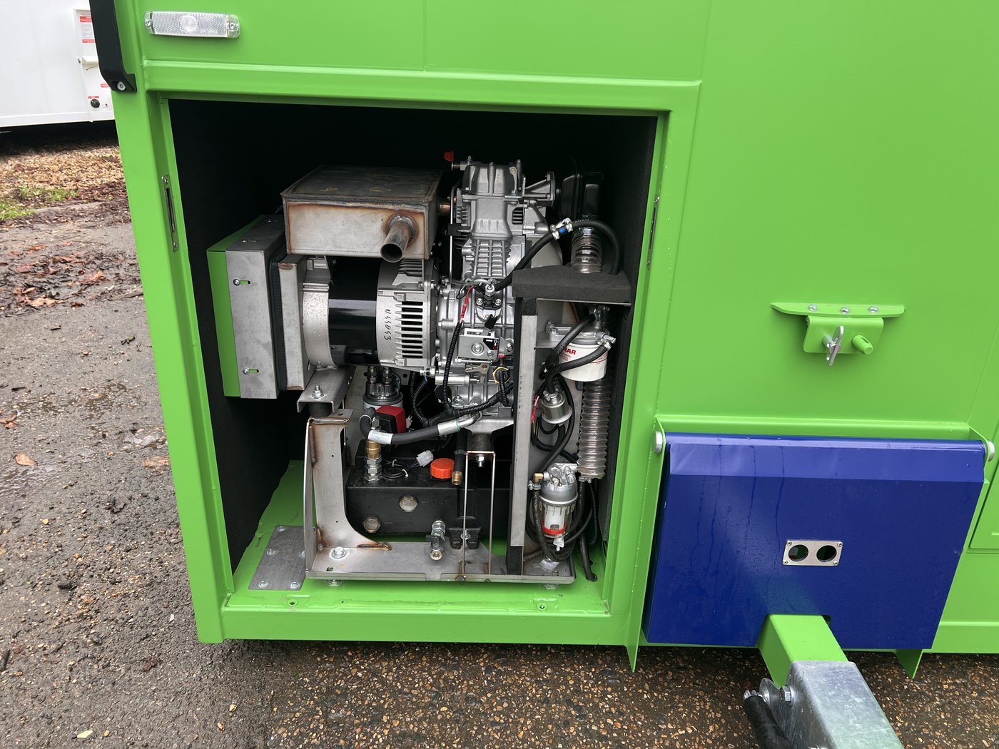
Fig. 24 — Generator with cover removed. Check oil level at this access point.
¶ Automatic Start/Stop — Generator Setpoints
The generator is controlled by the Siemens S7 PLC (see wiring diagram, Fig. 26). Three independent trigger conditions can each start the generator; all three must be satisfied for it to stop.
¶ Condition 1 — Battery State of Charge
| Parameter | Normal Mode | Quiet Hours |
|---|---|---|
| Start when SOC falls below | 45% | 20% |
| Start delay | 5 sec | 5 sec |
| Stop when SOC rises above | 85% | 50% |
| Stop delay | 0 sec | 0 sec |
¶ Condition 2 — Battery Voltage
| Parameter | Normal Mode | Quiet Hours |
|---|---|---|
| Start when voltage drops below | 50.0 V | 50.0 V |
| Start delay | 20 sec | 20 sec |
| Stop when voltage rises above | 54.5 V | 54.5 V |
| Stop delay | 20 sec | 20 sec |
¶ Condition 3 — Active AC Load
| Parameter | Normal Mode | Quiet Hours |
|---|---|---|
| Start when load exceeds | 7,000 W | 7,500 W |
| Start delay | 20 sec | 20 sec |
| Stop when load drops below | 6,000 W | 6,500 W |
| Stop delay | 120 sec | 120 sec |
¶ Conditions 4 and 5 — Node-RED (Thermal Protection)
- Inverter over-temperature warning sustained for more than 20 seconds → generator starts; warning cleared for 20 seconds → generator stops
- Inverter overload warning → same logic
¶ Pre-Deployment Checks
- Oil level — unlock the two front locks on the generator compartment door (Fig. 23); remove the generator cover; check oil is within range using the dipstick
- Fuel level — check the fuel gauge near the fuel tank
¶ Automated Pre-Start Safety Checks
Before each automatic start, the system verifies:
- Oil pressure — within the normal range (PLC input I12)
- Engine temperature — within the normal range (PLC input I13)
- Fuel level — sufficient
If any check fails, the generator will not start. An oil pressure fault requires a service engineer visit.
¶ Emergency Shutdown Triggers
The generator stops immediately if:
- The E-Stop is pressed (PLC input I11)
- The smoke detector activates
¶ Solar Panels
3,150W array: 4 × 315W roof-mounted panels and 6 × 315W wall-mounted panels (Figs. 4–7).
- Position the unit with the tow hitch facing south for maximum generation
- Clean panels regularly using a soft damp cloth or soft brush — do not use hard brushes or chemical cleaning products
- Extendable roof tray: release the two spring bolts on either side; use the centre handle to pull the tray out fully. Always push it back fully and secure with the spring bolts before towing
¶ Electrical System — Wiring Reference
The following diagrams cover all electrical sub-systems. They are intended for use by qualified engineers and service personnel. All conductor sizes are indicated on each diagram.
¶ Diagram 1 — Generator PLC Box
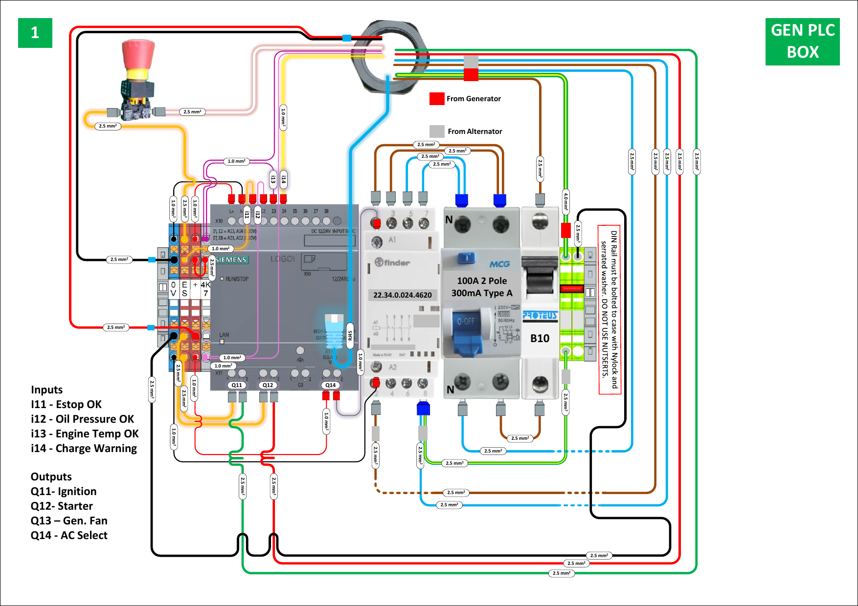
Fig. 26 — Generator PLC Box. Siemens LOGO! PLC with Finder relay, 100A RCD, and B10 MCB. Inputs: I11 E-Stop OK, I12 Oil Pressure OK, I13 Engine Temp OK, I14 Charge Warning. Outputs: Q11 Ignition, Q12 Starter, Q13 Generator Fan, Q14 AC Select.
¶ Diagram 2 — Engine Wiring Loom
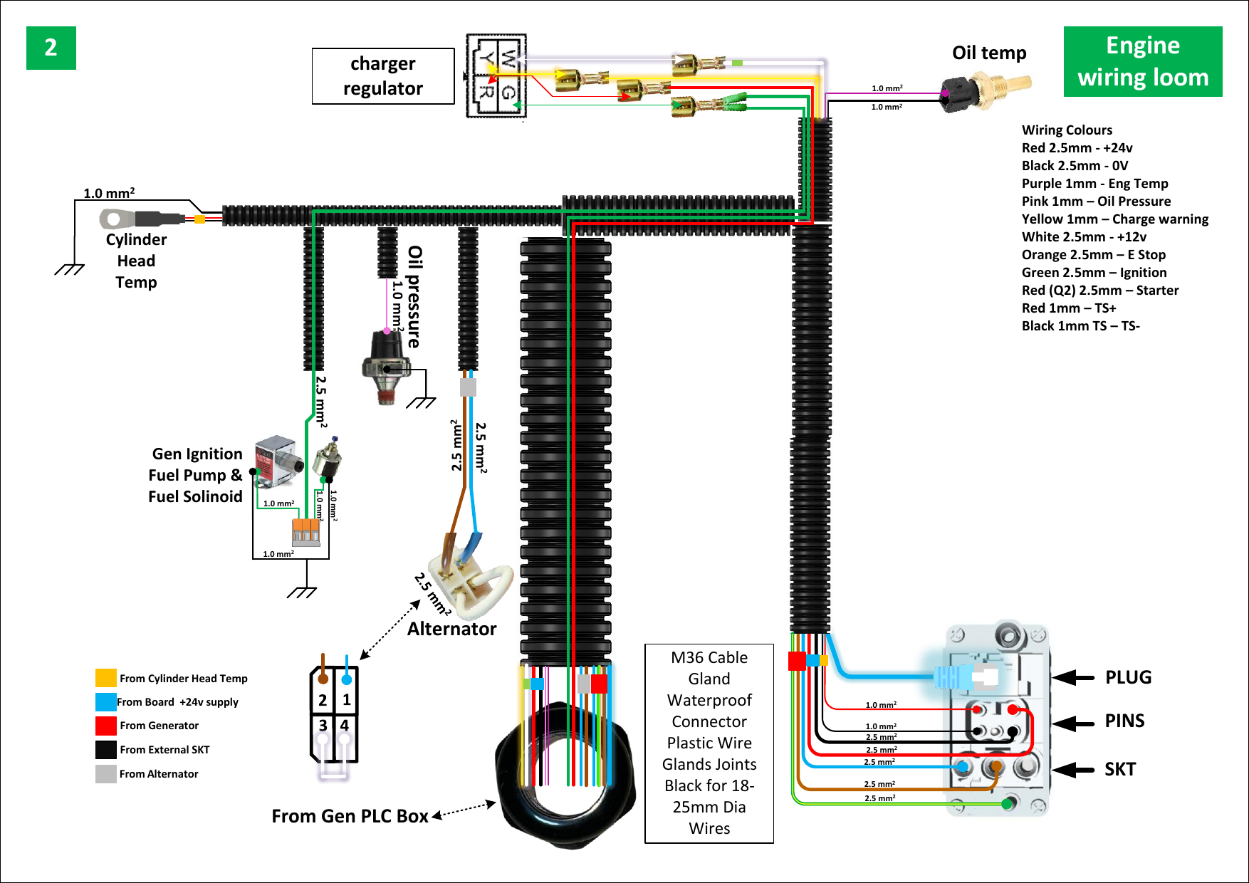
Fig. 27 — Engine wiring loom. Connects the Gen PLC Box to engine sensors (oil pressure, engine temp, charge warning) and actuators (ignition, starter, fuel pump). M36 waterproof cable gland at the connector.
Wiring colour code:
| Colour | Size | Signal |
|---|---|---|
| Red | 2.5mm² | +24V |
| Black | 2.5mm² | 0V |
| Purple | 1.0mm² | Engine temperature |
| Pink | 1.0mm² | Oil pressure |
| Yellow | 1.0mm² | Charge warning |
| White | 2.5mm² | +12V |
| Orange | 2.5mm² | E-Stop |
| Green | 2.5mm² | Ignition |
| Red (Q2) | 2.5mm² | Starter motor |
| Red | 1.0mm² | TS+ |
| Black | 1.0mm² | TS− |
¶ Diagram 3 — Engine Loom to 24V Board
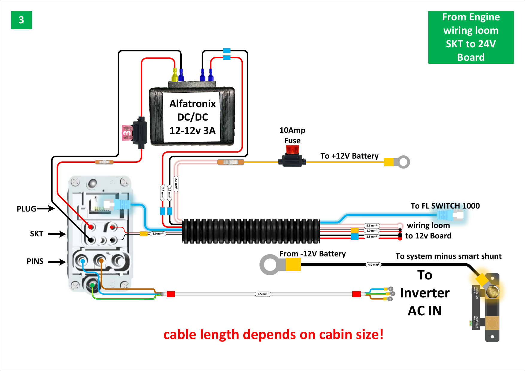
Fig. 28 — Engine loom to 24V Board. Includes Alfatronix DC/DC converter, 10A battery fuse, and connections to the 12V board, FL Switch, and inverter AC input. Note: cable lengths depend on cabin size.
¶ Diagram 4 — AC Input and Inverter/Charger
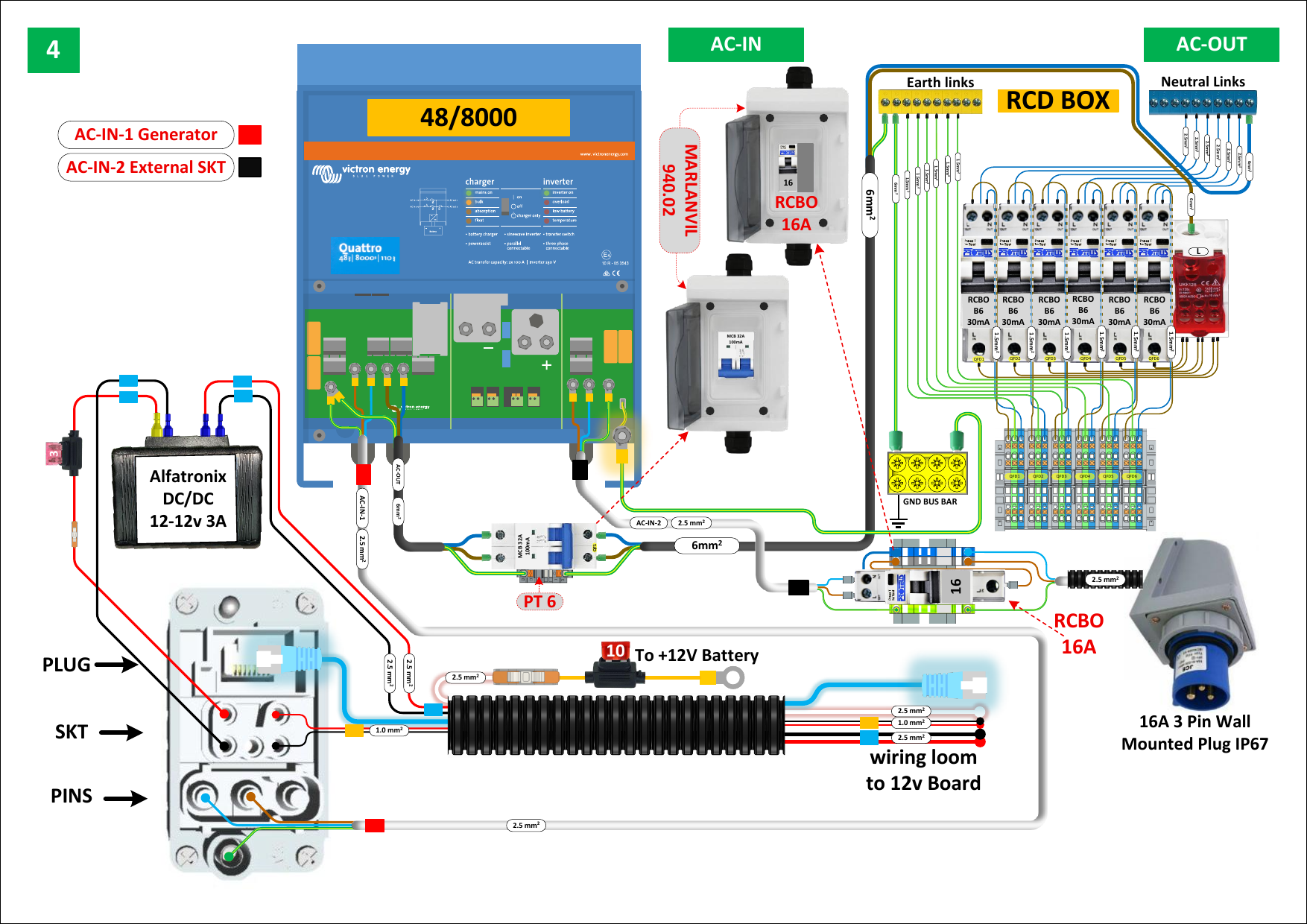
Fig. 29 — AC input and Victron Quattro 48/8000 inverter/charger wiring. AC-IN-1 (generator, red) and AC-IN-2 (external AC socket, black) are separate protected circuits. Alfatronix DC/DC converter also shown.
¶ Diagram 5 — Cerbo GX System Overview
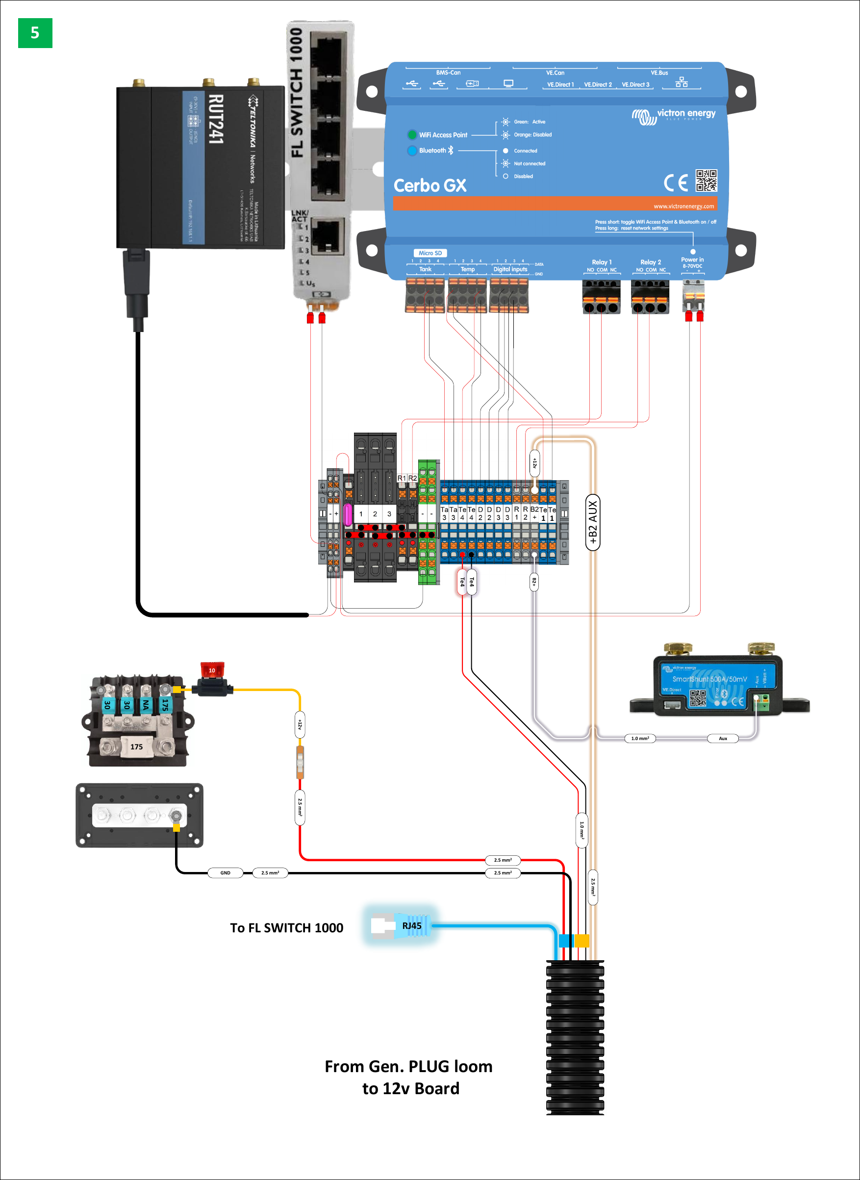
Fig. 30 — Cerbo GX system: management controller connected to 4G telemetry (RUT241), Ethernet switch, SmartShunt, and the 24V auxiliary board.
¶ Diagram 6 — AC Distribution (RCD Box)
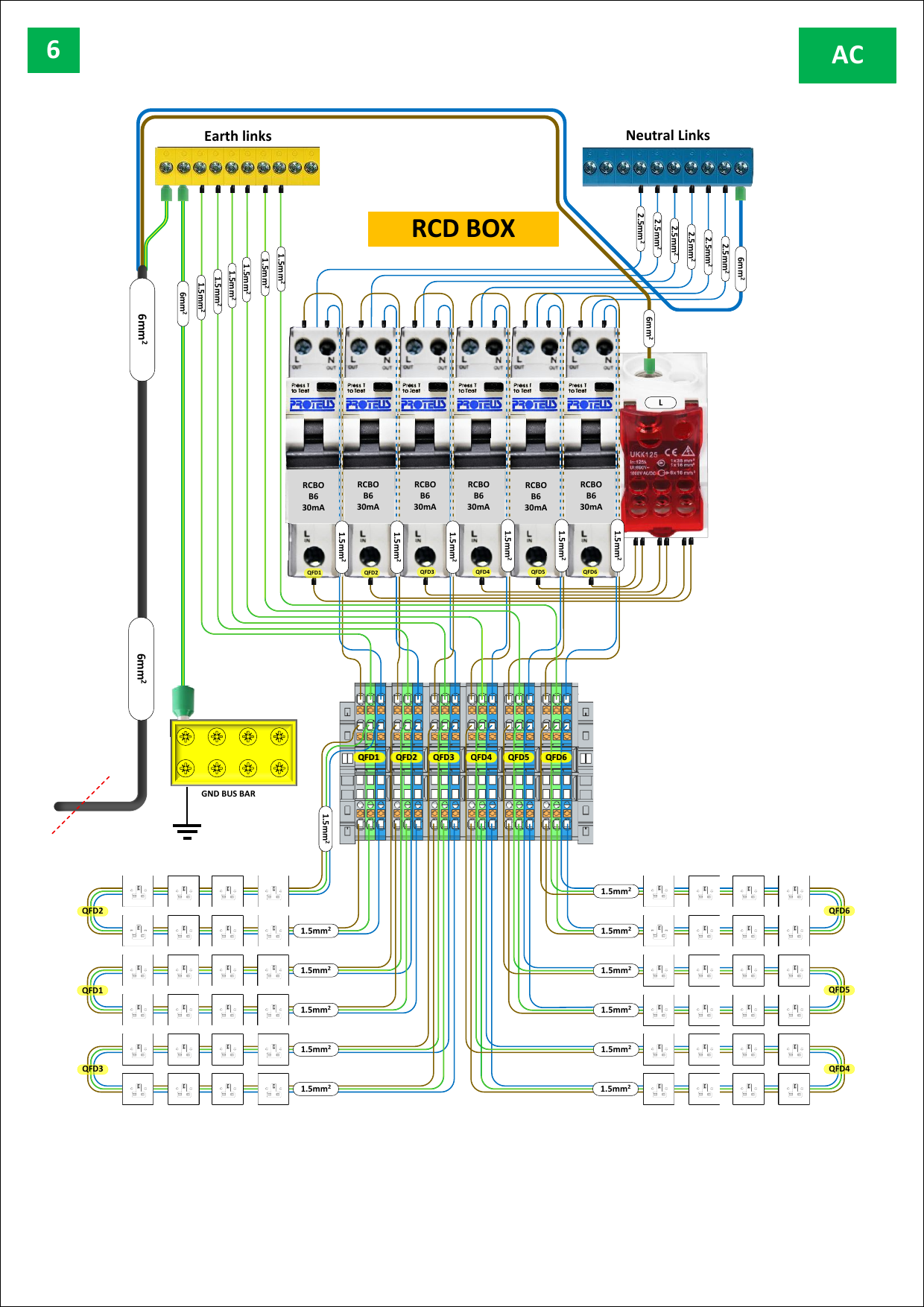
Fig. 31 — AC distribution. Six RCBO B6 30mA devices (QFD1–QFD6) each protect a zone of charging compartment sockets. Earth links and neutral links shown at top.
¶ Diagram 7 — DC System
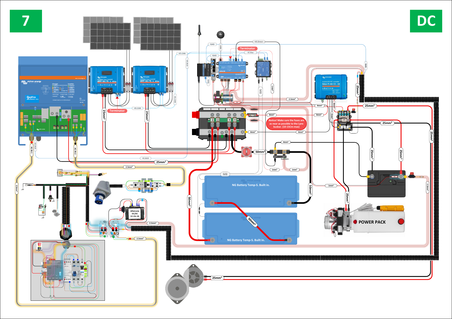
Fig. 32 — DC system: solar generation, battery storage, and DC distribution. Two MPPT 150/70 charge controllers, Lynx fuse/distributor, and two 5.12 kWh lithium-ion batteries. Hydraulic power pack connected to the DC bus.
¶ Diagram 8 — Cerbo GX Connections (Detail)
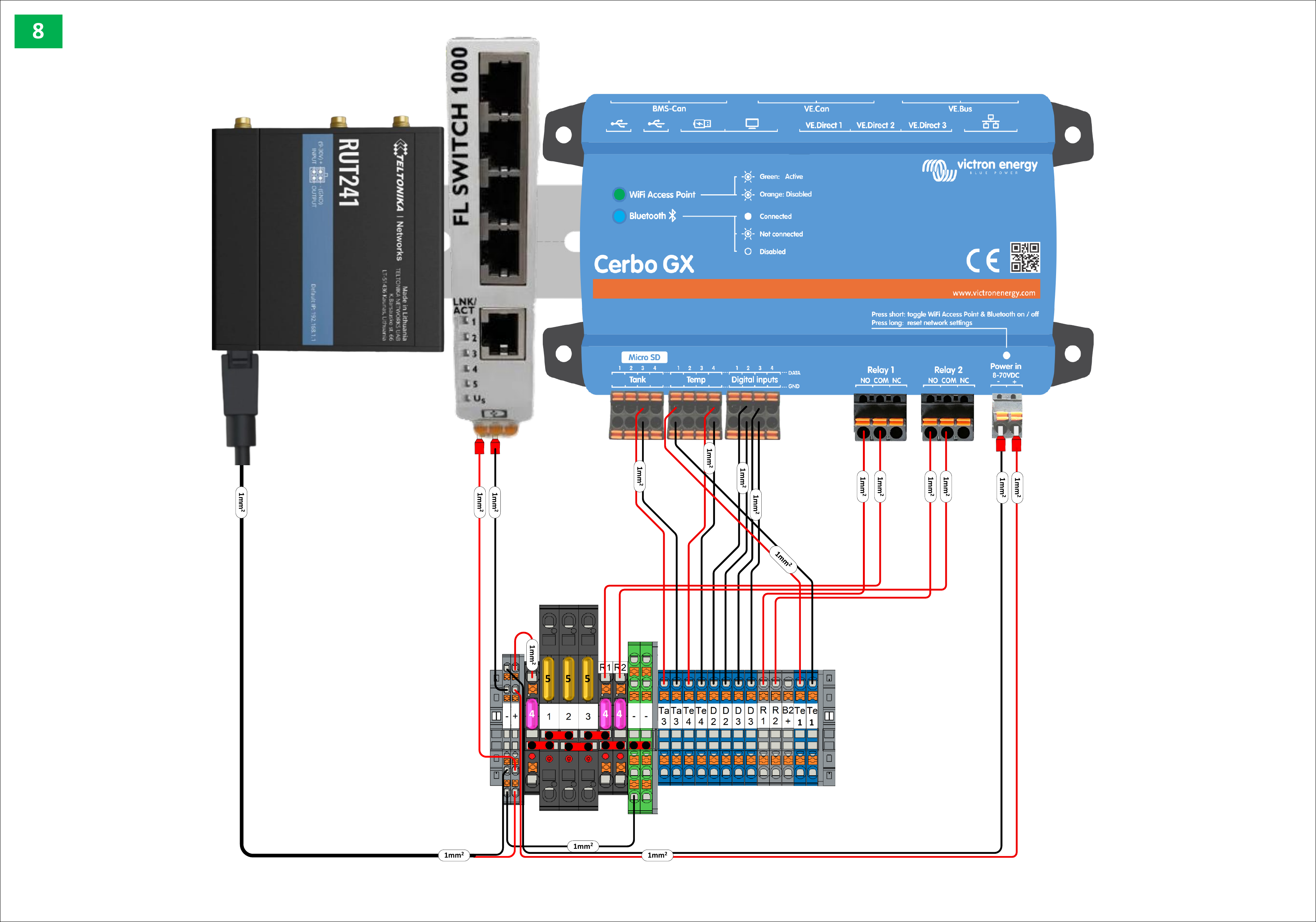
Fig. 33 — Cerbo GX terminal block connections in detail. All sensor inputs, relay outputs, and bus connections are shown.
¶ Diagram 9 — Earthing and Grounding
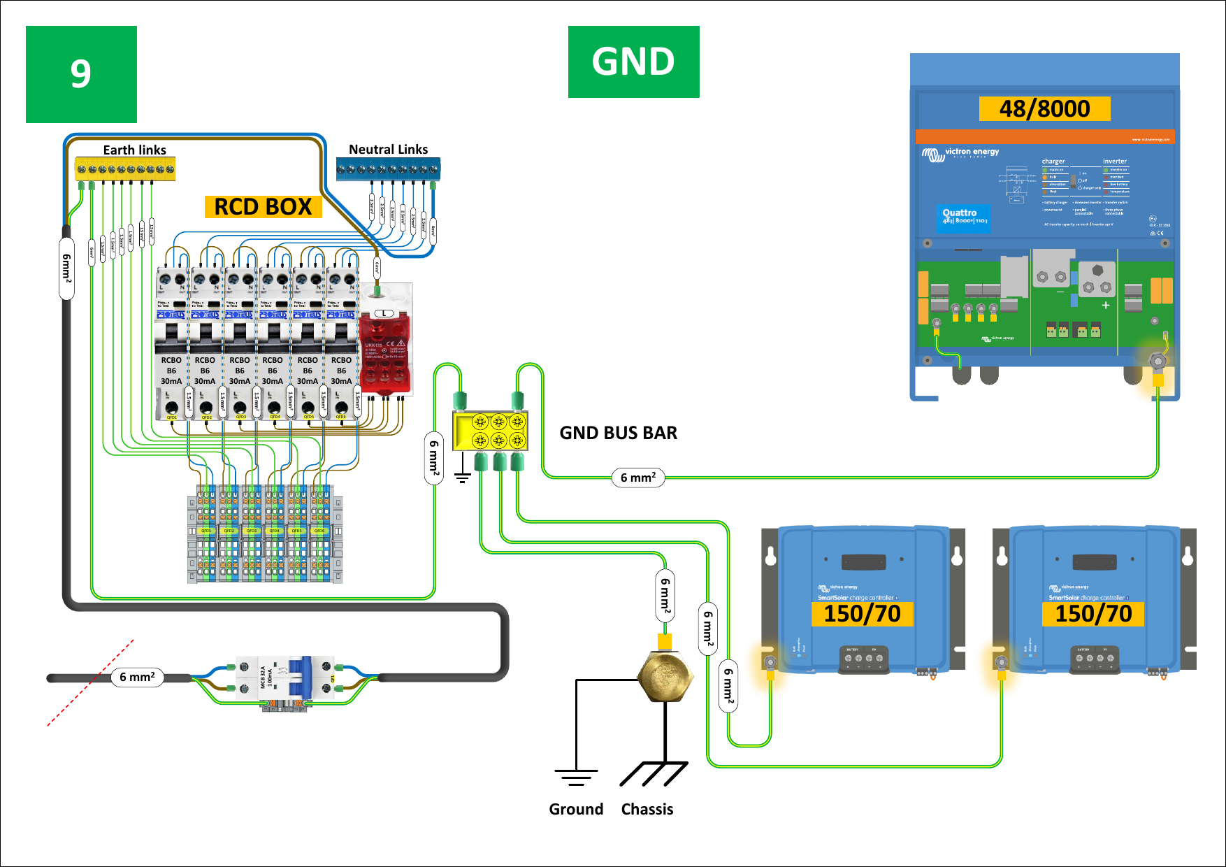
Fig. 34 — Earthing and grounding. All AC earth references connect to a central GND bus bar, which is bonded to the chassis ground point. Both MPPT charge controllers are individually earthed.
¶ Diagram 10 — Smoke and Heat Detector
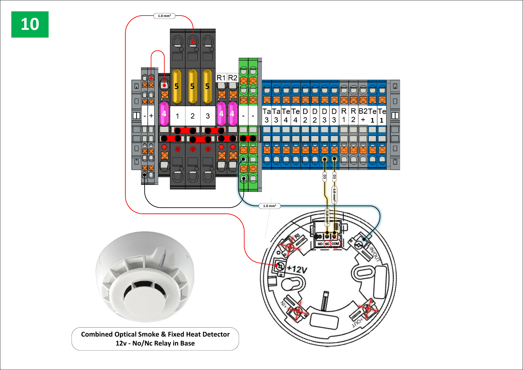
Fig. 35 — Smoke and heat detector wiring. Combined optical smoke and fixed heat detector with 12V No/Nc relay in base, connected to the Cerbo GX digital inputs. Alarm triggers immediate inverter shutdown.
¶ Diagram 11 — PIR Lighting
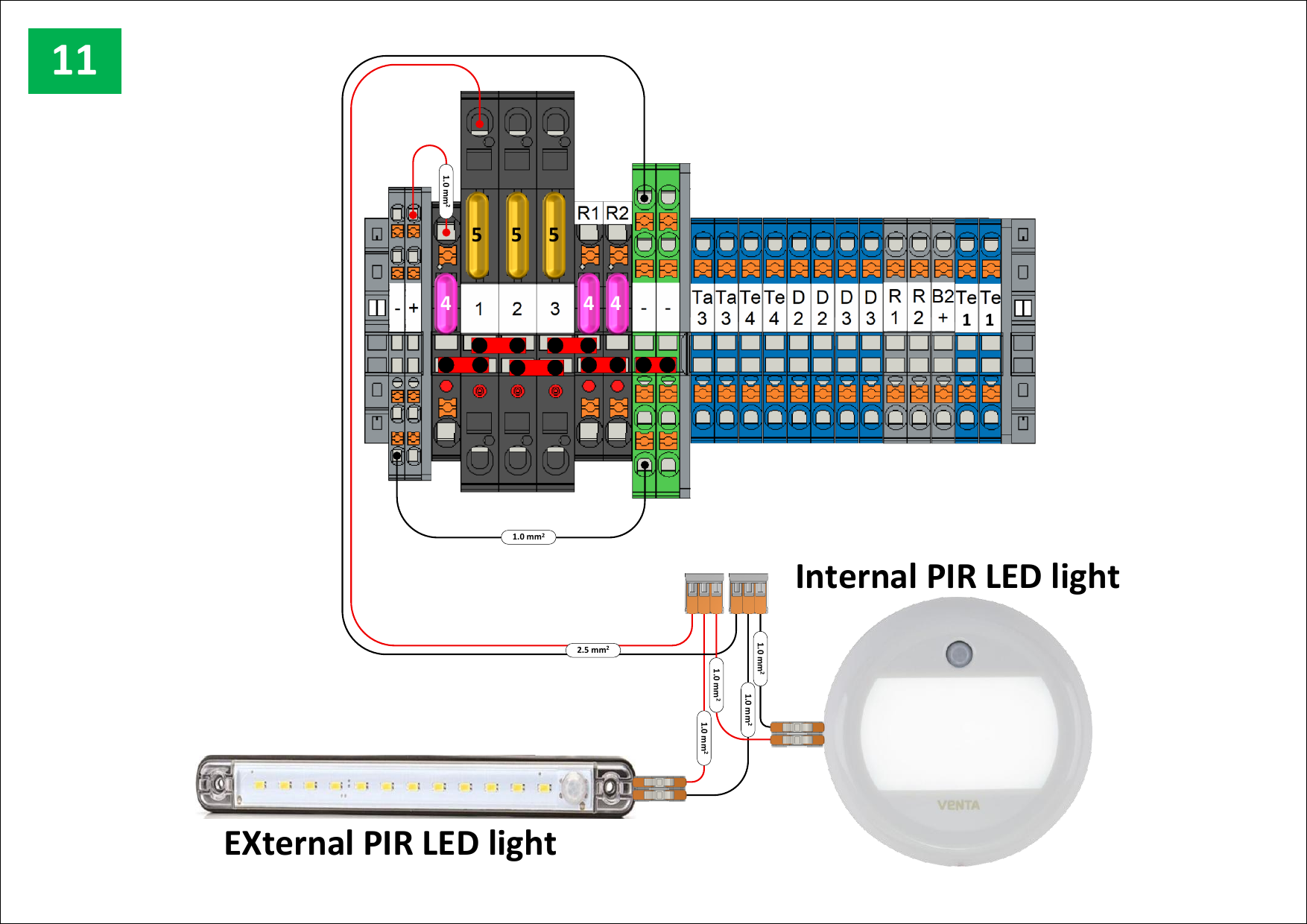
Fig. 36 — PIR lighting circuit. Internal Venta PIR LED light (round, ceiling-mounted) and external strip PIR LED light above the access door. Both are 24V DC and controlled by their own motion sensors.
¶ Diagram 12 — Battery Heater, Fuel Tank Sensor, and Temperature Monitoring
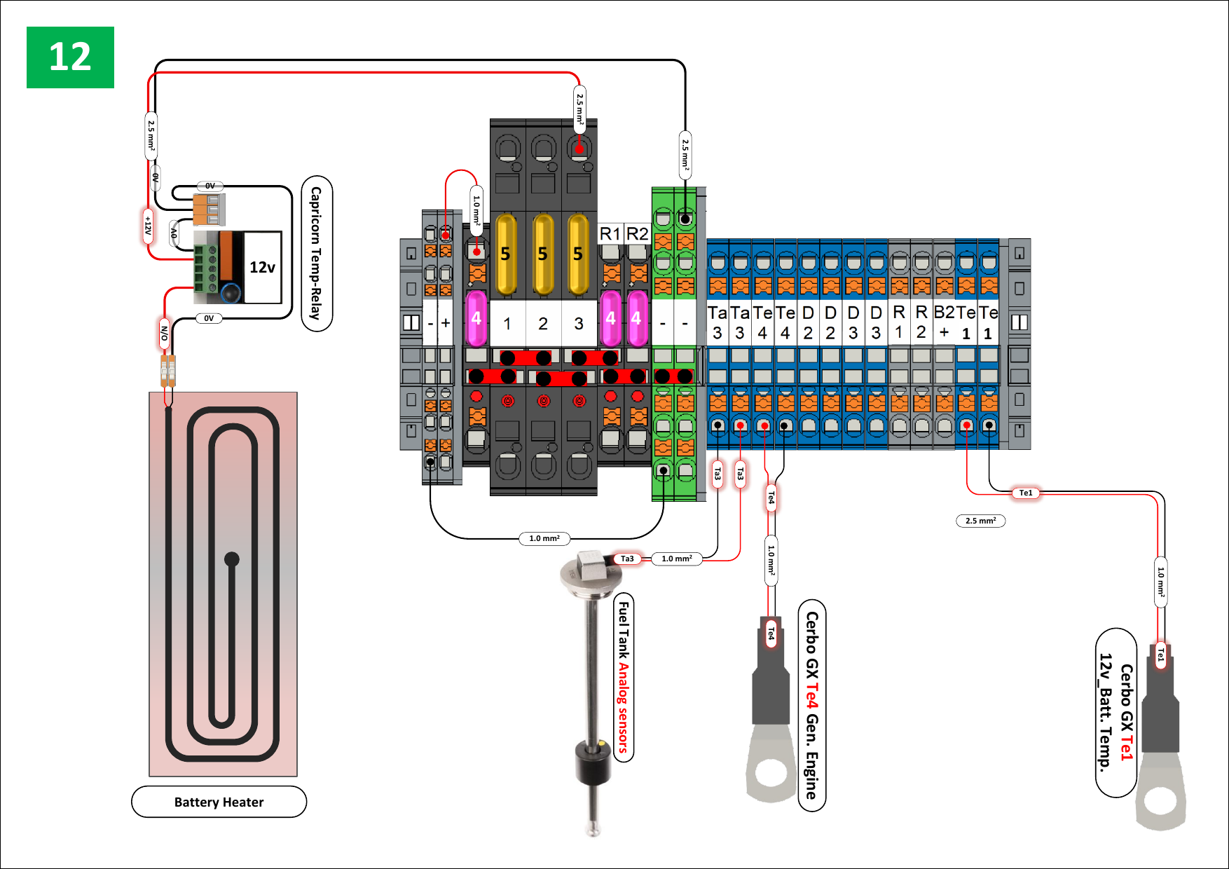
Fig. 37 — Battery heater, fuel tank level sensing, and temperature monitoring. The Capricorn Temp-Relay switches the battery heater pad on/off based on battery temperature. The Cerbo GX monitors: fuel tank level (analog float sender → Ta3), generator engine temperature (Te4), and 12V battery temperature (Te1).
¶ Diagram 13 — Hydraulic Power Pack
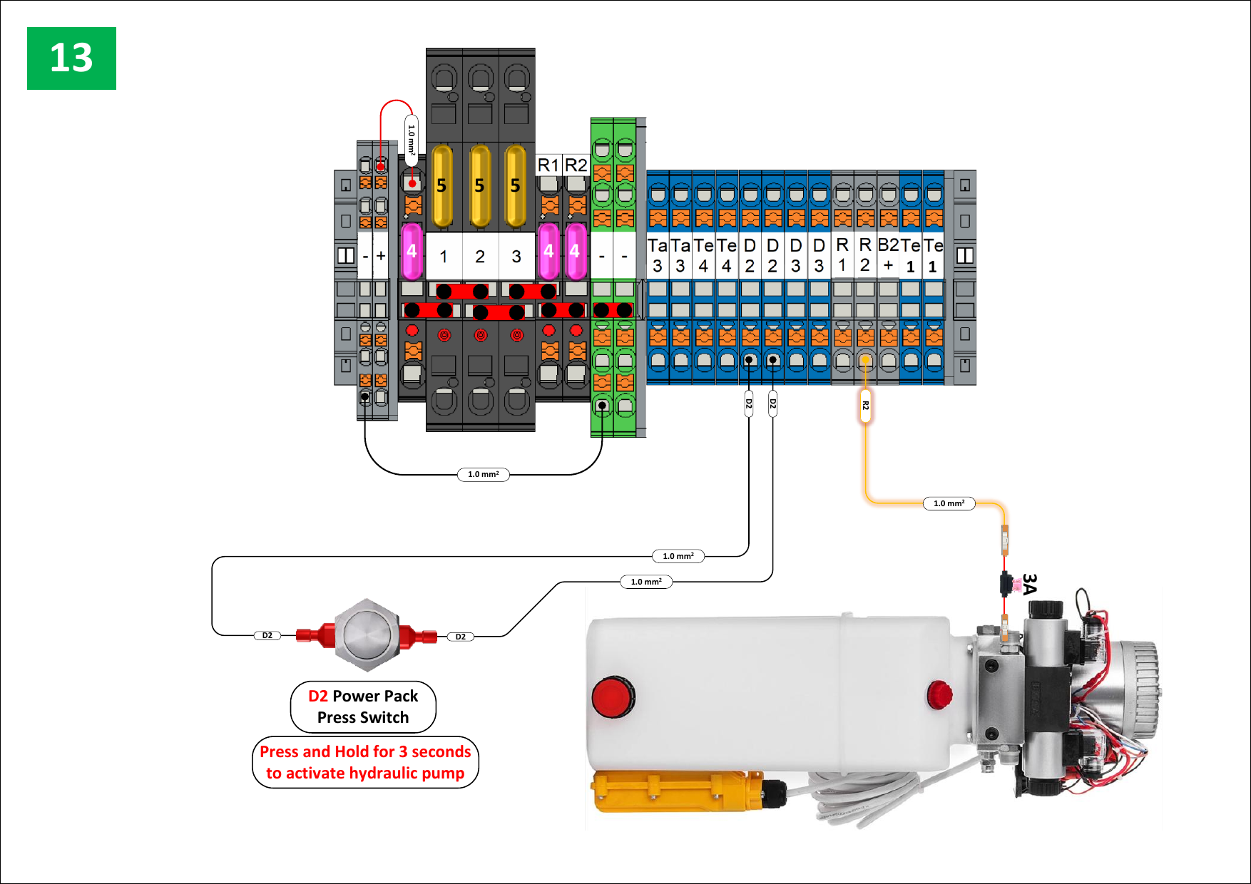
Fig. 38 — Hydraulic power pack circuit. D2 Power Pack Press Switch: press and hold for 3 seconds to activate the hydraulic pump. The pump remains active for 5 minutes. All other electrics are disabled during pump operation.
¶ Diagram 14 — Generator Cooling Fan
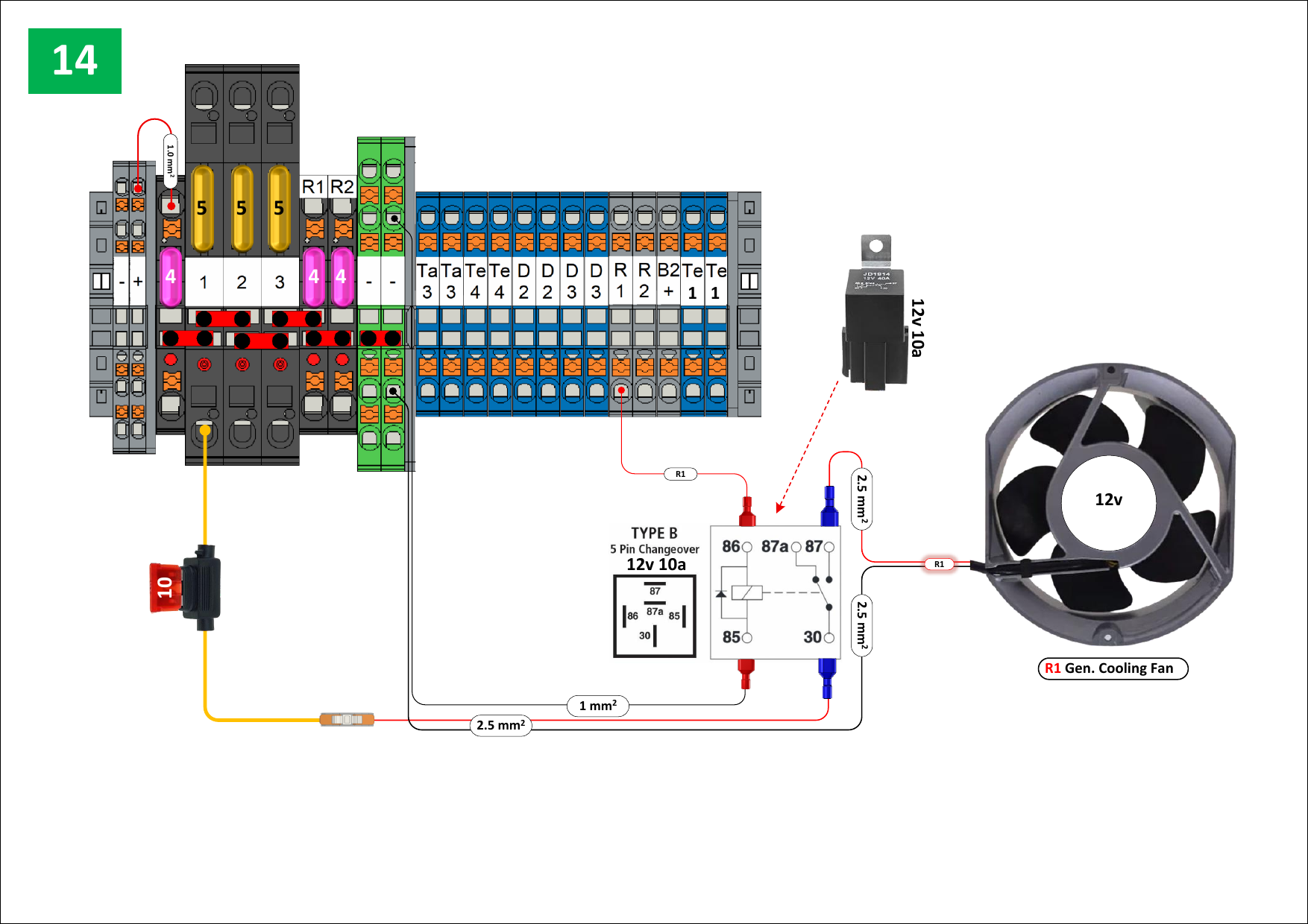
Fig. 39 — Generator cooling fan (R1). Cerbo GX Relay 1 controls a Type B 5-pin changeover relay (12V 10A), which in turn switches the generator cooling fan. Fan runs whenever the generator demand flag is active.
¶ Diagram 15 — Terminal Block Reference
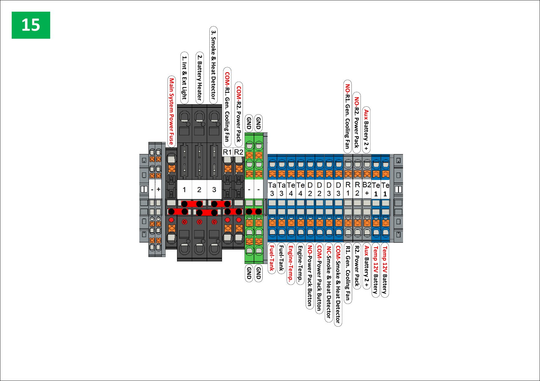
Fig. 40 — Complete terminal block reference. Shows all circuit names and terminal positions across the full DIN rail assembly. Use this as the authoritative reference for all field wiring.
Terminal block assignments (summary):
| Terminal | Circuit |
|---|---|
| Main System Power Fuse | System power feed |
| 1 | Internal and external lights |
| 2 | Battery heater |
| 3 | Smoke and heat detector |
| R1 COM | Generator cooling fan |
| R2 COM | Power pack |
| Ta3 | Fuel tank (analog) |
| Te4 | Engine temperature |
| D2 | Power pack button |
| NO/NC | Smoke and heat detector |
| COM | Generator cooling fan |
| R2 | Power pack relay |
| Aux Battery 2+ | Auxiliary battery positive |
| Te1 | 12V battery temperature |
¶ Diagram 16 — Victron Quattro Cooling Fan
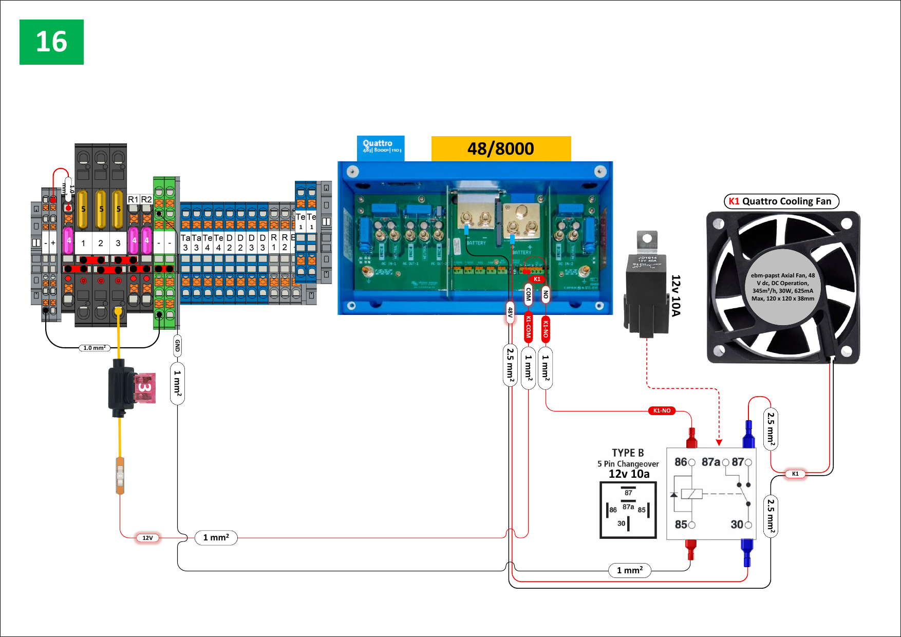
Fig. 41 — Victron Quattro cooling fan (K1). The Quattro's internal relay activates a Type B changeover relay, which switches the ebm-papst axial fan (48V DC, 30W, 120mm). Fan operates when the Quattro is under load.
¶ Software and Control Architecture
The unit uses a Victron Cerbo GX running Node-RED, connected to a Siemens S7 PLC that controls the physical generator relays. Setpoints are configured via the GX Touch HMI screen on the Cerbo GX. Remote telemetry and monitoring are provided by a Teltonika RUT241 4G router (Figs. 30 and 33).
¶ PLC I/O Summary
Inputs:
| Address | Signal |
|---|---|
| I11 | E-Stop OK |
| I12 | Oil Pressure OK |
| I13 | Engine Temperature OK |
| I14 | Charge Warning |
Outputs:
| Address | Function |
|---|---|
| Q11 | Ignition relay |
| Q12 | Starter motor relay |
| Q13 | Generator cooling fan relay |
| Q14 | AC Select relay |
¶ Node-RED Flow Structure
| Tab | Purpose |
|---|---|
| Gen | Generator start/stop logic, pre-start safety checks, PLC heartbeat |
| Logs | System event logging to files on the Cerbo GX |
| Debug | Manual generator control interface (engineers only — see below) |
| Relays and Digital Input | Relay state monitoring, BMV power saving, smoke alarm response |
¶ Generator Control Logic (Gen Tab)
- A Virtual Generator node (Victron library) tracks generator state:
0= off,1= starting,2= running,3= stopping - On each state change, a function node checks E-Stop status and generator state
- If E-Stop is pressed or state is
0, the generator will not start - When all conditions are satisfied, the
40r17_network_demandflag changes totrue, communicating to the PLC via Ethernet and energising the ignition relay (Q11) - A second flow continuously monitors engine temperature (I13) and charge warning (I14) every second — if either signal is lost, the Virtual Generator state resets to
0 - A heartbeat pulse is generated every 0.5 seconds to verify PLC communications
¶ Relays and Digital Input (Safety Tab)
- BMV power saving: if SOC drops below 18%, the SmartShunt relay opens, disconnecting the BMV to save power; relay closes again when SOC rises to 22% or above
- Generator cooling fan: the
PLCgendemandflag drives the cooling fan relay via Q13 - Smoke alarm response: if the smoke detector returns alarm code
9, a function node commands the Victron Quattro to switch to inverter state1(Off), cutting all AC output to the charging sockets
¶ Manual Generator Control (Engineers Only)
This procedure is intended for software developers and qualified service engineers only. Do not use during normal operation.
- Enable manual mode: on the Node-RED Debug dashboard, press
1on relay address6.7(Manual Enable). This prevents the automatic control flow from conflicting with manual inputs - Turn on ignition: press
1on relay address6.0(Ignition) - Crank the starter: press
1on relay address6.1for a maximum of 5 seconds, then immediately press0
Critical: If
0is not pressed on relay6.1within 5 seconds, the starter motor will continue to run and will damage itself or the engine.
¶ RCD Board

Fig. 25 — RCD distribution board (IP67 enclosure). Contains the main Siemens RCBO and MCG breaker.
The RCD board is located inside the unit. For the full circuit layout, including the six zone RCBOs protecting the charging socket groups, refer to wiring diagram 6 (Fig. 31).
¶ Diagnostics
Note: All electrics are disabled while the hydraulic rams are activated (5-minute timeout). Verify that the rams are not active before commencing any fault diagnosis.
¶ Display Screen Warnings — Check First
| Warning | Action |
|---|---|
| E-Stop pressed | Twist the E-Stop button clockwise to release |
| Rams enabled | Wait for the 5-minute timeout to expire, or complete the deployment/retraction procedure |
| Low fuel | Refuel with HVO biofuel or diesel |
¶ No Power to Charging Sockets
- Check the cabin isolator switch position (Fig. 16)
- Check the RCD box — all switches should be in the correct (ON/up) position (Fig. 25)
- If on external AC: verify the external RCBO is set correctly — an incorrect setting drains the battery and prevents the generator from starting
- Check battery SOC and voltage via the display screen or telemetry
- Check the E-Stop is released (OUT)
- Check battery terminal connections
- If SOC is below the generator start threshold: wait for solar charging, or connect external AC
¶ Generator Not Starting
- Check the fuel level (telemetry display or fuel gauge in the front locker)
- Check the oil pressure — a failed oil pressure sensor (I12) will prevent any start attempt
- Check both the generator E-Stop (at the PLC box) and the main unit E-Stop
- If the generator attempts to start but shuts down immediately: check the fuel pump
¶ Generator Running But Not Charging
- Check the RCD located between the generator output and the MultiPlus input
¶ No Solar Charging
- Verify the unit is positioned in direct sunlight (tow hitch facing south)
- Clean the solar panels
- Check the RCD near the SmartSolar MPPT charge controllers
- Check the solar panel isolator switch if fitted
¶ No 24V Power (Lights, etc.)
- Confirm the E-Stop is released
- Work through the diagnostics above for battery/power faults
¶ Hydraulic Rams Not Operating
- Press and hold the silver button for 2 full seconds — this is required before the rams will respond
- Confirm the E-Stop is released
- Check battery SOC — rams will not activate below 30% SOC; all ram function is cut off below 15% SOC
¶ Maintenance — Service Schedule
| Check | Daily | Weekly | Monthly | 6-Monthly | Annual | Before Towing |
|---|---|---|---|---|---|---|
| Check fuel level | ✓ | ✓ | ||||
| Check generator oil | ✓ | |||||
| Clean solar panels | ✓ | |||||
| Check CO monitor function | ✓ | |||||
| Check CO monitor sensor | ✓ | |||||
| RCD board electrical check | ✓ | ✓ (on delivery) | ||||
| Check tyre inflation | ✓ | |||||
| Check tyre condition | ✓ | |||||
| Check brake setting and operation | ✓ | ✓ | ||||
| Brake function check (road test) | ✓ | ✓ | ||||
| Grease axle locking pins and coupler | ✓ | ✓ | ||||
| Check all road lights | ✓ | |||||
| Check breakaway cable | ✓ | |||||
| Check coupler function | ✓ | |||||
| Grease exposed metal parts | ✓ | |||||
| Check anti-vandal cover operation | ✓ | |||||
| Check drawbar coupling wear | ✓ | |||||
| Check braking system for corrosion and defects | ✓ | |||||
| Heater service checks | ✓ | |||||
| Replace heater heat exchanger, sensor, and exhaust | — | — | — | — | After 10 years | — |
¶ Maintenance — Procedures
¶ Changing a Wheel — Single Axle (12ft/16ft)
Safety: Always fit ram props before working beneath the unit. Never work under an unsupported load.
Preparation:
- Disconnect from the towing vehicle; retrieve the hydraulic cylinder props from storage
- Raise the cabin on the rams until the wheels clear the ground
- Place one prop on each cylinder leg; secure each with its pin and clip
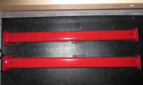
Fig. 54 — Ram cylinder props (red). Four required — one per corner. Never work under the cabin without all four fitted.
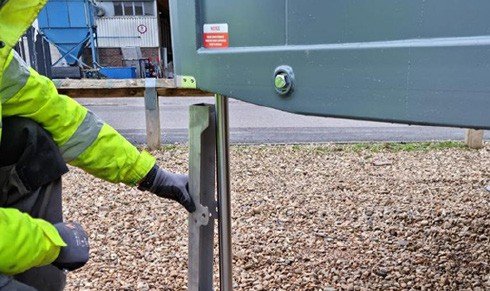
Fig. 55 — Fitting the ram prop to the cylinder leg.
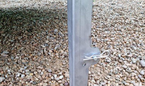
Fig. 56 — Pin and R-clip securing the ram prop. Check all four before proceeding.
Procedure:
- Remove the wheel guard panel — unscrew all fasteners using an impact driver and withdraw the panel

Fig. 57 — Wheel guard panel removal. Use an impact driver; remove all perimeter screws.
- Loosen and remove the wheel nuts using an impact driver

Fig. 58 — Removing wheel nuts with an impact driver.
-
Remove the wheel; repair or replace as required
-
Refit the wheel; tighten nuts in a star pattern (see Fig. 59) to 160 Nm
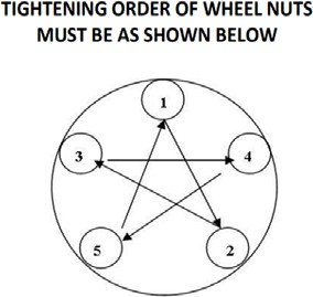
Fig. 59 — Wheel nut tightening order. Star pattern only — not circular.
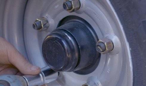
Fig. 60 — Final torque to 160 Nm.
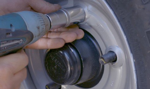
Fig. 61 — Fitting the wheel to the hub.
-
Set tyre pressure to 70 psi
-
Refit the wheel arch panel; replace all screws
-
Check wheel rotates freely in the forward direction
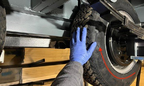
Fig. 62 — Confirm free forward rotation before removing props and lowering.
- Remove the props; lower the cabin; stow the props and remote control
¶ Changing a Wheel — Double Axle (20ft/24ft)
- Tyre size: 185/70 R13
- Tyre pressure: 87 psi
- Wheel nut torque: 160 Nm
- Leaf spring support bolt torque: 60 Nm
The full procedure involves raising and lowering the cabin on the rams multiple times to access the axle pins and leaf spring bolts. Refer to the base manual, section 8.1B, for the complete step-by-step procedure.
¶ Brake Setting — Single Axle
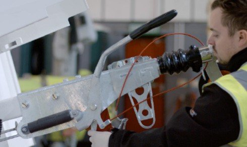
Fig. 63 — Overrun coupling assembly. The handbrake lever controls the parking brake; the draw tube must be fully extended before brake setting.
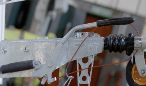
Fig. 64 — Coupling detail showing brake cable routing and compensator bar connection.
Preparation:
- Uncouple on level ground; raise the cabin fully; fit all four ram props
- Lower the parking brake handle; ensure the draw tube is fully extended from the overrun coupling
Fig. 65 — Lowering the handbrake lever and extending the draw tube — required before any brake adjustment.
- Verify brake cables are not under tension — adjust the M8 nuts on the cable compensator bar if necessary
- Verify the brake rod is not under tension — adjust the M10 lock nut if necessary
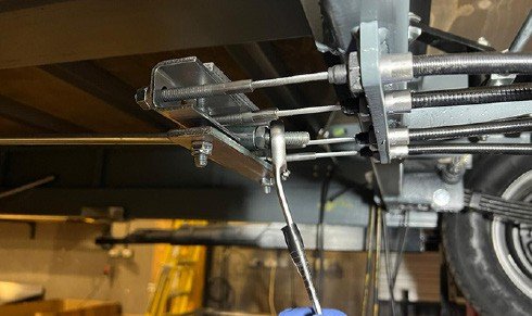
Fig. 66 — Brake rod and compensator bar assembly (under chassis). Verify no tension before proceeding.
Setting procedure:
- Tighten the brake adjuster screw clockwise until the wheel cannot be turned by hand — rotate wheels in the forward direction only
Fig. 67 — Brake cable adjuster. Tighten clockwise until wheel locks; back off ~180° until it turns freely.
- Back off anti-clockwise by approximately half a turn (180°) until the wheel turns freely
- Repeat for each wheel
- Set the cable compensator bar perpendicular (90°) to the direction of travel; secure with M8 nuts
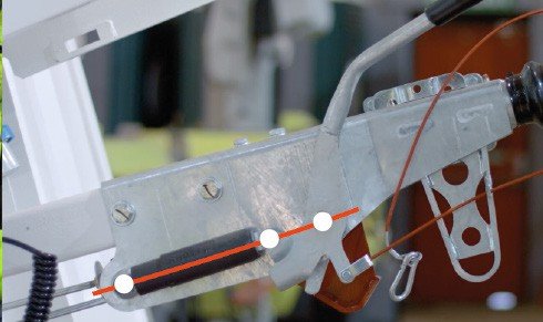
Fig. 68 — Compensator bar set perpendicular to direction of travel and locked with M8 nuts.
- Set the brake rod with neither tension nor free play; tighten the outer locknut
- Firmly activate the handbrake repeatedly to re-seat all components — do not force it beyond its normal rest position
- Position the handbrake lever so all three pivot points are aligned; the brake reaction lever should just contact the handbrake lever
- Verify that the reaction lever has 10–15 mm of free movement away from the handbrake lever when pushed manually
- Confirm the compensator bar remains perpendicular
- Rotate the wheels forward — verify they turn freely with no rubbing
Warning: Rotating wheels in the reverse direction at any point may trigger the auto-reverse mechanism. If this occurs, check for faults and repeat the entire procedure from step 1.
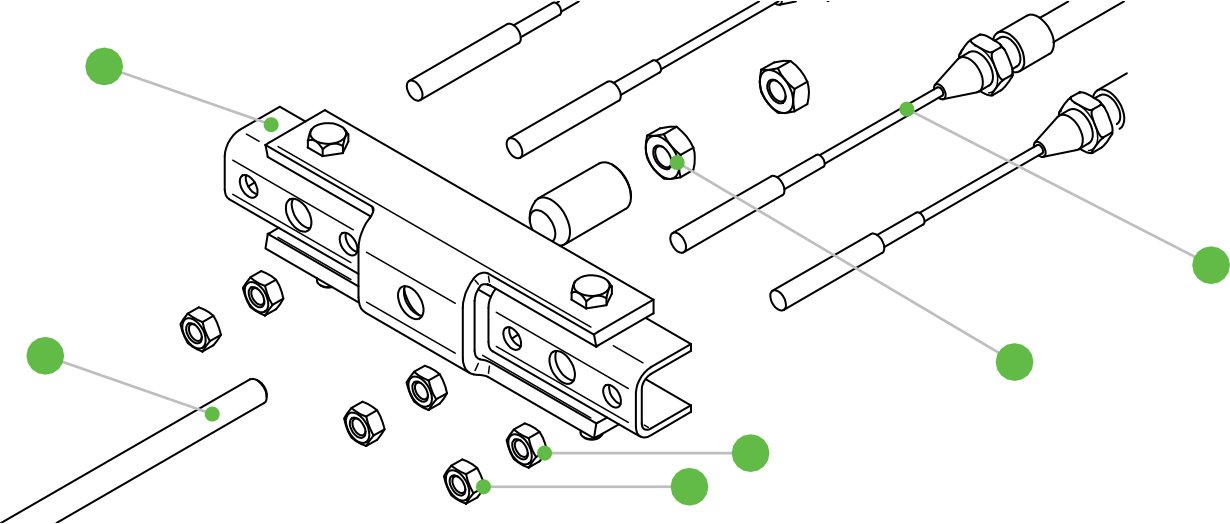
Fig. 52 — Brake rod assembly components.
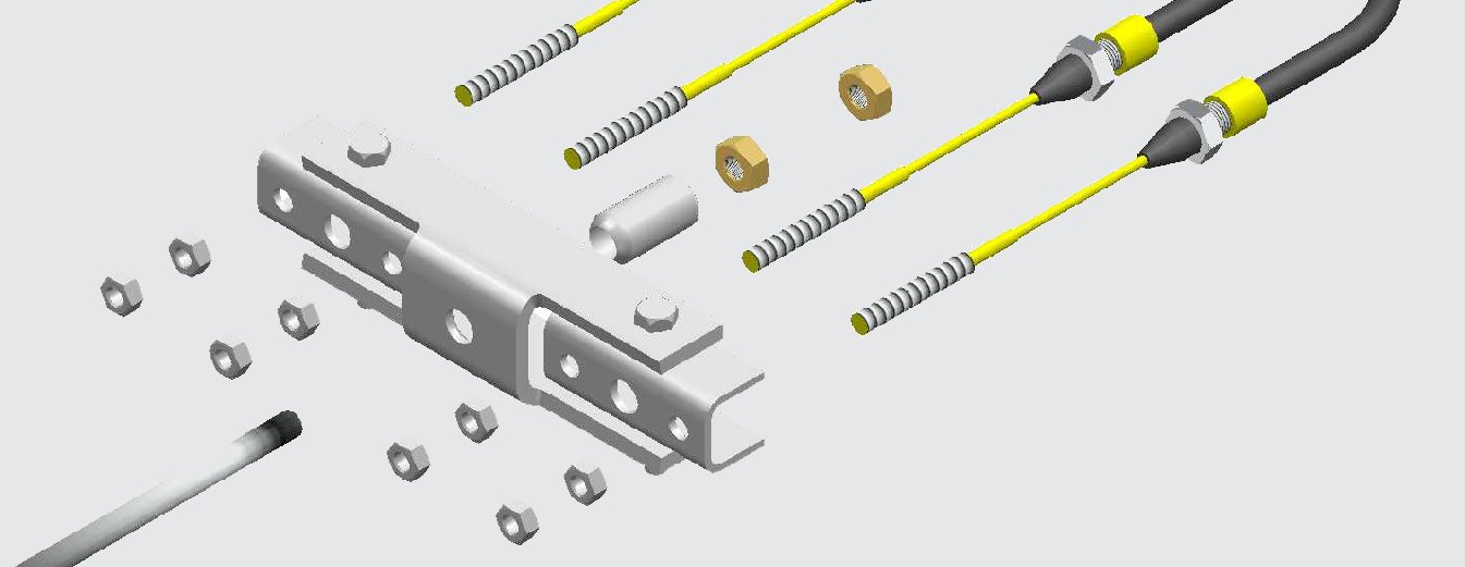
Fig. 53 — Brake cable compensator bar assembly.
¶ Brake Road Tests
| Test | Speed | Manoeuvre |
|---|---|---|
| Road Test A | 20–25 mph | Gradual firm stop in a straight line |
| Road Test B | 35–40 mph | Firm, steady stop; no wheel lock-up |
| Road Test C | 50 mph | Reduce to 30 mph; accelerate back to 50 mph; repeat 3–4 times |
The cabin must brake evenly with no pulling to one side. Readjust and re-test if braking is uneven.
Bedding in: Brakes may not reach optimum efficiency during the first 500 miles. If the unit is parked for an extended period or in damp conditions, chock the wheels and release the handbrake.
Adjustment check interval: Before each journey, push the bottom of the brake reaction lever forward — if movement exceeds 45–50 mm, the brakes require readjustment.
¶ RCD Board Check
On delivery to site, and every 6 months:
- Open the RCD board cover; verify the main RCD paddle is UP (ON) (Fig. 25)
- Press the TEST button — the paddle must move to the DOWN (OFF) position and cut all circuits
- If the paddle does not move: the RCD is faulty — do not use the electrical system until it has been repaired by a qualified electrician
- Reset: push all paddles to the ON (up) position
¶ Heater Monthly Checks (Service Technician)
- Check the air inlet and outlet for foreign matter
- Clean the external surfaces
- Check for corrosion or loose electrical connections
- Check the combustion air inlet and exhaust for damage or blockage
- Check the fuel line for leaks
- Run the heater for at least 10 minutes to prevent mechanical seizure
After 10 years: replace the heat exchanger, overheat sensor, and exhaust system.
¶ Warranties
| Component | Warranty Period |
|---|---|
| Unit (manufacturer) | 12 months from the date of sale |
| Anti-corrosion (stainless steel chassis) | 25 years |
| SOLARFlow™ electrical system | 5 years (extendable to 10 years) — covers Cerbo GX, SmartShunt/BMV, Easy Solar, solar charger, Battery Protect, and display screen |
| Lithium-ion batteries | 3 years |
| Solar panels | 2 years |
| REDBOX Infinity generator | 12 months or 2,000 operating hours (whichever comes sooner) |
Warranty exclusions:
- Neglect, misuse, or unauthorised modifications
- Damage resulting from abuse, impact, or failure to follow these instructions
- Repairs carried out by non-authorised persons
- Transport costs associated with warranty claims
- Fair wear and tear
- Non-standard parts, or consequential damage arising from their use
The warranty may be voided if scheduled servicing and inspections are not carried out. Any welding, drilling, cutting, or other structural modification requires written approval from Boss Cabins Ltd before work begins.
¶ Legal and Safety
¶ Towing — Legal Requirements
| Requirement | Detail |
|---|---|
| Maximum tow speed | 50 mph (80 km/h) |
| Unit dimensions (body) | 3,650 × 2,300 × 2,630 mm (L × W × H) |
| Towing length / height | 4,775 mm / 2,900 mm |
| Net weight | 2,211 kg |
| Fuel tank capacity | 50 litres |
| Axle rating | Single axle, 2,500 kg |
| Starting battery | 12V AGM leisure battery (generator start circuit only) |
| Towing vehicle | Must be rated for the unit's MTPLM; consider GTW and rear axle loading |
| Towing bracket | Must comply with Directive 94/20/EC and be fitted and used in accordance with the manufacturer's instructions |
| Registration plate | 520 × 120 mm, correctly positioned — must display the same registration mark as the towing vehicle |
| Towing mirrors | If the unit (2,300 mm wide) is wider than the towing vehicle, extension mirrors are required. Mirrors must be "e" marked. M1 vehicles (cars): Class III mirrors — 4 m wide × 20 m behind. M2/M3/N2/N3 vehicles: Class II mirrors — 4 m wide × 30 m behind |
| Road lighting | It is an offence to tow without adequate and properly functioning lighting. All of the following must be fitted and working: |
| VIN plate | Located on the front bulkhead beneath the anti-vandal cover. Contains: MTPLM (position 5), maximum coupling load (position 6), maximum axle load (position 7) |
Required road lighting:
| # | Type | Colour | Qty |
|---|---|---|---|
| 1 | Number plate lamp | White | 1–2 |
| 2a | Stop lamp | Red | 2 |
| 2b | Rear position lamp | Red | 2 |
| 2c | Direction indicator | Amber | 2 |
| 3a | Fog lamp | Red | 1 |
| 3b | Reversing lamp | White | 1 |
| 4 | Triangular reflector | Red | 2 |
| 5 | End outline marker lamp | Red and White | 2 |
| 6 | Side marker lamp | Amber | 4 |
| 7 | Front position (side) lamp | White | 2 |
Driving requirements:
- Use high-intensity warning beacons or hazard lamps when manoeuvring on public roads
- Use a banksman if visibility is limited when reversing
- Cordon off the area when raising or lowering the unit
- Carry out a risk assessment before siting — check ground conditions, underground services, overhead cables, and clearance distances
¶ Driver Licence Requirements
The Charge Space has a Maximum Technically Permissible Laden Mass (MTPLM) of 2,300 kg. This is above the 750 kg threshold at which towing entitlement becomes licence-category dependent. Drivers holding a B1 or higher licence category may tow any Boss Cabins trailer. For Category B (standard UK car licence) holders, entitlement depends on the date the licence was issued.
Key terms:
| Term | Meaning |
|---|---|
| MTPLM | Maximum Technically Permissible Laden Mass (of the trailer) |
| MRO | Mass in Running Order (unladen/ex-works mass) |
| MAM | Maximum Authorised Mass (max weight of towing vehicle) |
| GTW | Gross Train Weight (trailer + towing vehicle combined) |
| MTM | Maximum Towable Mass (max the towing vehicle is allowed to tow) |
Cat B licence issued before 1 January 1997: Generally permitted to tow, subject to GTW not exceeding 8,250 kg and trailer MTPLM not exceeding towing vehicle MRO. Check using a full flowchart if in doubt.
Cat B licence issued 1 January 1997 – 18 January 2013: May tow if trailer MTPLM does not exceed towing vehicle MRO, and GTW does not exceed 3,500 kg. Above these limits, a Category BE licence is required.
Cat B licence issued after 19 January 2013: May tow trailers up to 750 kg MTPLM freely. For trailers over 750 kg (this unit): MTPLM must not exceed towing vehicle MRO, and GTW must not exceed 3,500 kg. If either limit is exceeded, a Category BE licence is required.
At 2,211 kg net weight, this unit will typically require a Category BE licence for drivers who passed their test after January 1997, unless the towing vehicle has a sufficiently high MRO and the combined GTW remains within 3,500 kg.
Boss Cabins recommend that anyone towing one of their units undertakes professional training and accreditation.
¶ General Safety
Before using the unit and to avoid personal injury or equipment damage, read and understand these instructions in full. If there is anything you do not understand, do not use the equipment — contact Boss Cabins for advice.
- This equipment may only be operated on smooth, firm, level ground capable of bearing its weight under all weather conditions
- Before siting, carry out a risk assessment to identify: ground hazards (underground services, unstable ground), side hazards (buildings, trenches, clearances for exhaust and ventilation), and overhead hazards (power lines, communications cables, lighting systems)
- Do not operate, move, or use this equipment if you are under the influence of alcohol or drugs, or if you are tired or unwell
- Do not wear loose jewellery or clothing that may become trapped in the mechanism
- When manoeuvring the unit on a public road, use the towing vehicle's high-intensity warning beacons or hazard lamps. Use a banksman if visibility is limited
- When raising or lowering the unit, cordon off the area to create a safe zone — isolate the unit from members of the public and bystanders
- Wear suitable personal protective equipment when making adjustments to the unit
- If there is any doubt about the unit's condition: do not continue. Contact the supplier
¶ Key Safety Notices
- Tyre pressure: 70 PSI / 4.8 BAR (single axle, 12/16ft)
- Fuel: HVO biofuel or diesel only — do not use biodiesel
- Generator oil: SAE 15W-40
- Hydraulic remote control: unplug when not actively raising or lowering the unit
- No smoking or vaping inside the unit at any time
- Before towing: press E-Stop IN, stow all loose items, verify all lights are working
- Electrical work: always press the E-Stop IN before carrying out any electrical work inside the cabin
¶ Document Status — Outstanding Items
The following items are incomplete or pending further input from the product team.
| Section | Outstanding Item |
|---|---|
| Unit Layout | Annotated external and internal diagrams with numbered component callouts required |
| Specifications | |
| Warranties | |
| Decals | Update decal information for Charge Space-specific branding |
| Legal | Confirm whether fire suppression certification documentation is required in addition to VCA and BS 7671 |
| Diagnostics | Photos to accompany each fault procedure (generator fuel pump, RCD between generator and MultiPlus) |
| Software | Node-RED flow screenshots to be added to the Software/ folder in the source package |